Upside down F-shape antenna

An antenna and metal sheet technology, applied in the direction of antenna, electrical components, radiating element structure, etc., can solve the problems of difficult to achieve system frequency bandwidth requirements, high difficulty in adjusting antenna characteristics, and small operating bandwidth.

Inactive Publication Date: 2009-12-30
连展科技电子(昆山)有限公司
View PDF5 Cites 0 Cited by
  • Summary
  • Abstract
  • Description
  • Claims
  • Application Information

AI Technical Summary

Problems solved by technology

[0003] The built-in antennas currently used in mobile communication devices such as mobile phones, personal digital assistants (PDAs) and other products usually use an inverted-F antenna design, and have a complete ground plane under the antenna. The known inverted-F antenna Antenna design such as U.S. Patent No. 6,727,854 B2 "Inverted-F Flat Panel Antenna" (reference figure 1 ), which discloses a built-in antenna applied to mobile phones. The antenna mainly radiates the metal sheet part, which can be roughly divided into three current paths 10, 13, and 14 starting from the feed-in point 15 and the short-circuit point 16. Using the Different paths excite different resonant frequencies to synthesize dual-frequency operation that meets the requirements of the GSM / DCS frequency band; this type of inverted-F antenna design usually has a complete ground plane under the antenna, so its operating bandwidth is small and difficult To achieve the bandwidth requirements required by the system frequency band, and in order to form a broadband effect, multiple meandering current paths are required, which makes the antenna structure more complicated, and it is difficult to adjust the characteristics of the antenna in practical applications

Method used


Image

  • Upside down F-shape antenna
  • Upside down F-shape antenna
  • Upside down F-shape antenna

Examples


Embodiment 2

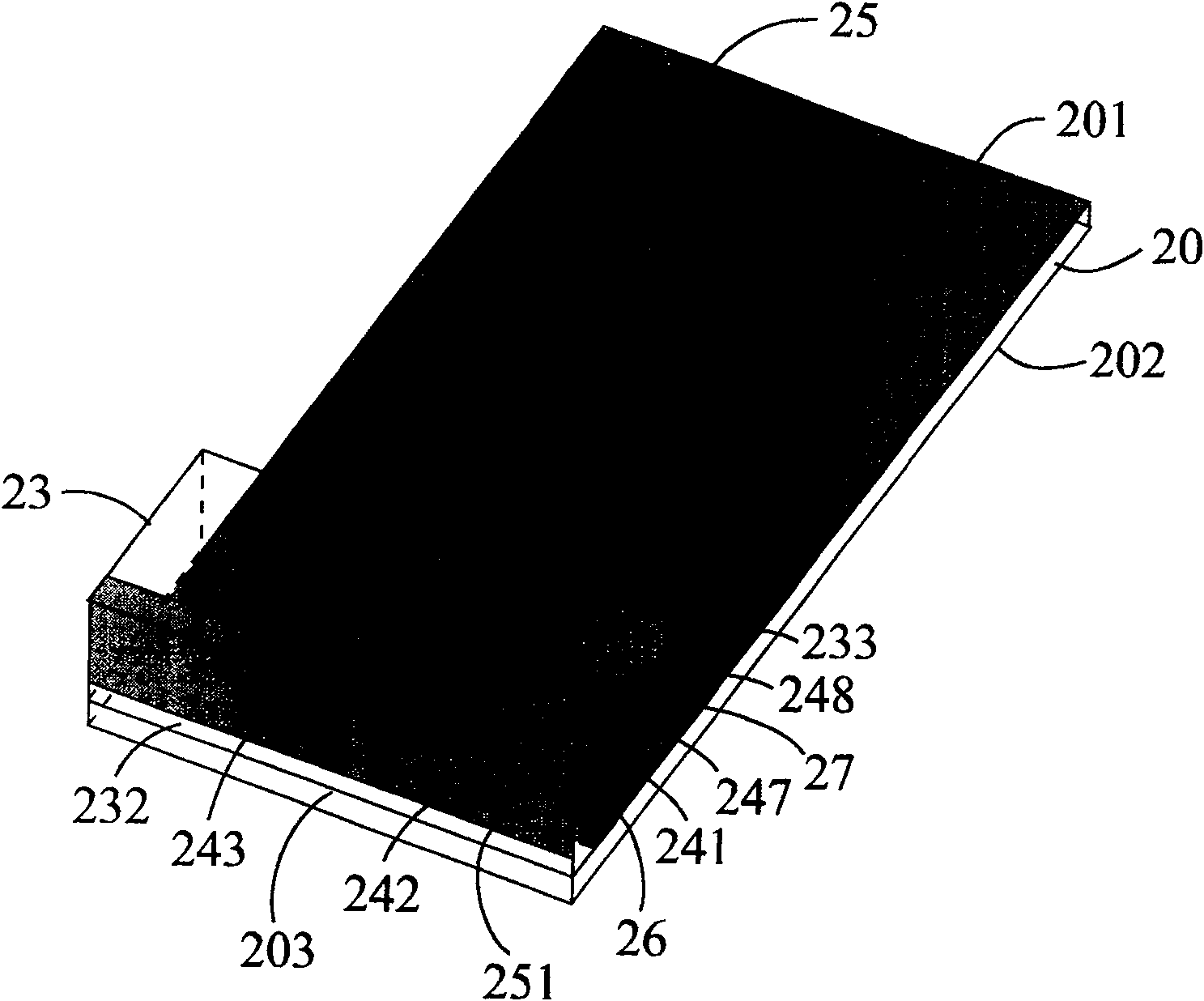
[0011] like figure 2 Shown is an embodiment 2 of the inverted-F antenna of the present invention, which includes: a microwave substrate 20, the microwave substrate 20 has a first surface 201 and a second surface 202; a dielectric substrate 23, located on the microwave substrate Above the first surface 201 of 20, the dielectric substrate 23 has an upper surface 231, two first side surfaces 232 and two second side surfaces 233, and the dielectric substrate 23 is air or a plastic material with a dielectric constant close to 1; The first side 232 is close to a short edge 203 of the microwave substrate 20 and is substantially parallel to the edge 203, and the second side 233 is a side perpendicular to the first side 232, and the length of the first side 232 Greater than the second side 233; a radiating metal sheet 24, the radiating metal sheet 24 includes a connecting metal sheet 241, a first sub-radiating metal sheet 242, a second sub-radiating metal sheet 243, a third sub-radiat...

Embodiment 4

[0013] like Figure 4Shown is an embodiment 4 of the inverted-F antenna of the present invention, which includes: a microwave substrate 40, which has a first surface 401 and a second surface 402; a dielectric substrate 43, located on the microwave substrate 40 Above the first surface 401, the dielectric substrate 43 has an upper surface 431, two first side surfaces 432 and two second side surfaces 433, the dielectric substrate 43 is air or a plastic material with a dielectric constant close to 1; A side 432 is close to a short edge 403 of the microwave substrate 40 and is substantially parallel to the edge 403, while the second side 433 is a side perpendicular to the first side 432, and the length of the first side 432 is longer than The second side 433; a radiating metal sheet 44, the radiating metal sheet 44 includes a connecting metal sheet 441, a first sub-radiating metal sheet 442, a second sub-radiating metal sheet 443, and a third sub-radiating metal sheet 444 , a matc...


PUM


Abstract

This invention relates to a design for an inverse F type antenna including: a microwave base plate, a medium base, a radiation metallic sheet, a short circuit metallic sheet and a feed metallic sheet and the radiation metallic sheet also includes a connection metallic sheet, a first sub-radiation metallic sheet, a second sub-radiation metallic sheet, a third sub-radiation metallic sheet, a matched metallic sheet, slits, short circuit point and feed-in point, in which, the first sub-radiation metallic sheet is used in generating a first operation mode of the antenna, the second sub-radiation metallic sheet is used in generating a second operation mode of the antenna, the third sub-radiation metallic sheet is used in regulating the operational frequency and width of the second operation mode, the slits, the feed-in point and the short circuit point are used in regulating the impedance match and a notch is set at the earth side to increase the operation frequency width of the first operation mode.

Description

technical field [0001] The invention relates to an inverted-F antenna (inverted-F antenna), especially an antenna applied to wireless communication products. Background technique [0002] With the rapid development of wireless communication in recent years, the performance requirements of antennas have also gradually increased. In addition to the reduction in size, the antenna characteristics must also have the characteristics of multi-band or large bandwidth in order to meet market demand. Under the consideration of appearance and practical convenience, it is gradually moving towards the built-in antenna design. At the same time, because it needs to be hidden in the communication product case, the matching method between the antenna and the system ground plane is also relatively important. Different ground plane forms As well as the relative position of the ground plane and the antenna, it usually makes the design of the built-in antenna very different. Therefore, in a lim...

Claims


Application Information

Patent Timeline
Patent Type & Authority Patents(China)
IPC IPC(8): H01Q13/08H01Q1/38
Inventor 张秉宸林文发邱宗文萧富仁
Owner 连展科技电子(昆山)有限公司
Why Eureka
Try Eureka