Check patentability & draft patents in minutes with Patsnap Eureka AI!

Method for structural unloading in construction

A technology for building construction and supporting structures, which is applied in building construction, construction, building maintenance, etc. It can solve the problems of difficult control of the degree of unloading, occupation of construction, and huge construction difficulty of construction, and achieve obvious economic effects.

Inactive Publication Date: 2010-01-06
四川省西南建科建筑工程技术有限公司 +1
View PDF4 Cites 0 Cited by
  • Summary
  • Abstract
  • Description
  • Claims
  • Application Information

AI Technical Summary

Problems solved by technology

These two systems are difficult to control the unloading process and degree of component unloading; when vertical loads need to be unloaded in multi-storey buildings, due to the layer-by-layer transfer of loads, in order to achieve safe unloading requirements, it is necessary to The support system is set up in the alignment, so that the number of supports required in the construction is huge, occupying a large number of construction work surfaces, and bringing great construction difficulties to subsequent construction
At the same time, in the current unloading technology, the requirement of gradual loading after the completion of subsequent construction cannot be realized

Method used


Image

  • Method for structural unloading in construction
  • Method for structural unloading in construction
  • Method for structural unloading in construction

Examples


Embodiment 1

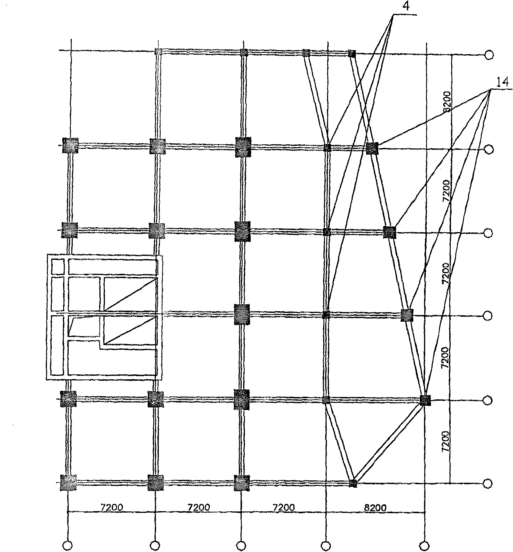
[0030] see Figure 1 to Figure 7 Shown is the application of the unloading and loading method of the present invention in floor reconstruction.

[0031] In a comprehensive office building, due to the need to change the use function of the floor, it is necessary to remove the column 4 to be pulled out on the third floor below the elevation of 11.3m (such as figure 2 shown), and the pulling column 4 below the elevation of 16.1m is removed (such as image 3 As shown), the beams and slabs on the second floor are removed to form a column-free space in the hall part of the floor. After the column 4 to be pulled is removed, the span of the beam increases to a maximum of 15.4 meters. The original structural force system has been greatly changed. Before the column 4 to be pulled is removed, the corresponding beam or other columns must be reinforced. The characteristics of this embodiment are that there are many layers (3 floors) of columns to be pulled out, and the number of columns...

Embodiment 2

[0035] Such as Figure 7 As shown, this project also encountered problems in the setting of one of the lifting points. The section of the shaft column is irregular and polygonal, and there is an inclined beam at the lifting point so that the sling cannot pass through. Therefore, the position of the lifting point is changed from the beam The lower opening of the steel beam is converted to the slab surface, and the steel beam is used to correct the column section when setting the lifting point, and then the upper and lower composite beams are connected by an adapter device, which successfully solves this problem. Other settings in this embodiment are the same as those in Embodiment 1.

Embodiment 3

[0037] Such as Figure 8 As shown in the figure, the reconstruction and reinforcement project of a large electrical room of a company, the reconstruction part is the gate of the large electrical room. The width of the doorway was changed from 8000mm to 10000mm; each side was widened by 1000mm, but the height of the bottom of the door lintel 18 could not be reduced. Moreover, the original doorway could be used at any time because the workshop could not stop production during the construction period. Due to the large span of the newly remodeled door opening, a steel column is supported in the upper part of the beam. In order to increase the long-term use safety of the door opening, this plan specially adds prestressed diagonal tie rods to unload and strengthen the door beam. Construction status: set steel backing plate connection at the top of the column and about one-third of the span of the door lintel. Use the prestressed oblique rods to unload part of the load generated by ...


PUM


Abstract

The invention discloses an unloading and loading method during construction. The invention applies an upward pulling force to a structure which needs to be unloaded so as to eliminate the vertical pressure of the structure, and the loading and unloading processes can be controlled at any time by a monitoring device and a sling force applying system; in accordance with the construction control requirements and stress requirements of all engineering components, control can be conducted by the vertical load to be unloaded or loaded by steps during unloading, which solves deficiencies of uncontrollable unloading, not application to multi-storeyed building structure, large number of necessary supports, high influence on the next construction and failure to control loading, etc. The invention is not only applicable to concrete structures, but also applicable to construction of other types of structures, such as steel structure, wooden structure and other combined structure, etc.

Description

technical field [0001] The invention relates to a method for structure unloading during building construction. Background technique [0002] In existing buildings or buildings under construction, because the owner needs to change the building function to increase the structural load or expand the column grid size; or the building is damaged due to natural factors, reducing the structural bearing capacity; or due to various reasons in the construction When the bearing capacity of the structure is insufficient, it is often necessary to reinforce the structural components. In structural reinforcement engineering, since the object of reinforcement is the completed building structure, the structure must be under stress before reinforcement. Due to the initial load of the structure, the structural members produce initial stress or initial deformation. Whether the initial stress of the component or the degree of initial deformation is eliminated or how much it is eliminated will d...

Claims


Application Information

Patent Timeline
Patent Type & Authority Patents(China)
IPC IPC(8): E04G23/04
Inventor 张瀑鲁兆红陶继勇唐则军邓典达陈晓帆陈江
Owner 四川省西南建科建筑工程技术有限公司
Features
  • R&D
  • Intellectual Property
  • Life Sciences
  • Materials
  • Tech Scout
  • Unparalleled Data Quality
  • Higher Quality Content
  • 60% Fewer Hallucinations
Learn More