Processor and method by using batten check to switch instruction mode

An instruction mode and processor technology, applied in the direction of the address formation of the next instruction, machine execution device, etc., can solve the problem that 32-bit instructions and 16-bit instructions cannot be mixed and stored, the program code storage space cannot be optimized, and mixed storage is in the Issues such as the same block

Inactive Publication Date: 2010-03-24
SUNPLUS TECH CO LTD
View PDF4 Cites 0 Cited by
  • Summary
  • Abstract
  • Description
  • Claims
  • Application Information

AI Technical Summary

Problems solved by technology

[0002] General processors have a 32-bit / 16-bit instruction mode, and switch between these two modes to save the space required for program code storage. , PC) to determine that the processor is in a 32-bit or 16-bit instruction mode, and use a branch (Branch) instruction to switch the value of the T bit in the program counter. The instruction mode switching is as follows figure 1 As shown, when the branch (Branch) instruction 220 is executed, it branches to (Branch to) the starting address Badd (1) stored in the 16-bit instruction and executes the 16-bit instruction. The +1 is used to switch the T bit To indicate that the processor is in the 16-bit instruction mode, when executing the branch (Branch) instruction 240, it is to branch to (Branch to) the address Badd (2) stored in the 32-bit instruction and execute the 32-bit instruction, the +0 is It is used to change the T bit to '0' to indicate that the processor is in the 32-bit instruction mode. There are ARM and MIPS processors that adopt this switching method, but the 32-bit instruction and 16-bit instruction that adopt this switching method Bit instructions need to be stored in different blocks, 32-bit instructions and 16-bit instructions cannot be stored in the same block, so the program code storage space cannot be optimized
[0003] Aiming at the problem that 32-bit instructions and 16-bit instructions cannot be mixed and stored in the same block, in the US Patent No. USP6,209,079B1 announcement, the most significant bit (Most Significant Bit, MSB) bit in the instruction code is used to determine the processing The appliance is in 32-bit or 16-bit instruction mode to solve the problem that 32-bit instructions and 16-bit instructions cannot be mixed and stored in the same block, such as figure 2 As shown, if the MSB at the 32-bit boundary is '1', the 32 bits represent a 32-bit instruction, and if the MSB at the 32-bit boundary is '0', the 32 bits represent two 16-bit instructions, If the MSB of the 16-bit instruction B is '0', it means two sequentially executed 16-bit instructions; if the MSB of the 16-bit instruction B is '1', it means two 16-bit instructions executed in parallel, There are M32R series processors that adopt this switching method. In this switching method, the 32-bit instructions and the 16-bit instructions do not need to be stored in different blocks, so as to achieve the purpose of increasing the program code density (Code Density). However, When executing branch (branch) or jump (jump) instructions, care must be taken to avoid jumping to the second half of a 32-bit instruction. Since the second half of the 32-bit instruction is not an executable instruction, it will generate Unexpected errors, so the jump address should be limited to word boundary or 32-bit boundary. For branch-and-link and jump-link and-link) instruction return address (return address) also needs to be limited to the word boundary (word boundary) or 32-bit boundary (32-bit boundary), such restrictions will increase the inconvenience of use, at the same time, using the above The processor of technology does not have any fault-tolerant design when executing branch or jump instructions, that is, when the processor generates a wrong jump address due to hardware or external interference, the processor will not be able to handle it and the entire system will be damaged. stagnation (halt), therefore, there are still many deficiencies in the design of the existing 32-bit / 16-bit instruction mode conversion method and there is a need for improvement

Method used


Image

  • Processor and method by using batten check to switch instruction mode
  • Processor and method by using batten check to switch instruction mode
  • Processor and method by using batten check to switch instruction mode

Examples


Embodiment Construction

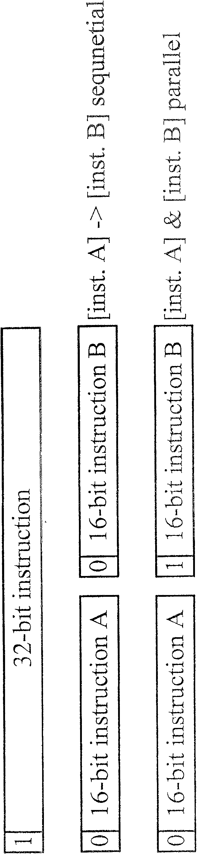
[0020] The processor and method for switching instruction modes using the same bit check of the present invention can respectively execute N-bit and 2N-bit mode instructions in N-bit and 2N-bit modes, N is an integer greater than or equal to 4, and the N-bit mode instructions are composed of An N-bit word group, the 2N-bit mode command is composed of two N-bit word groups, each N-bit word group contains P parity bits and (N-P) bit instruction codes, P is greater than or equal to 1 Integer, in the present embodiment, the N value is preferably 16 (also can be 8, 9, 32...), the P value is preferably 1, but it is only for the convenience of explanation, is not to limit the use of the present invention scope and powers.

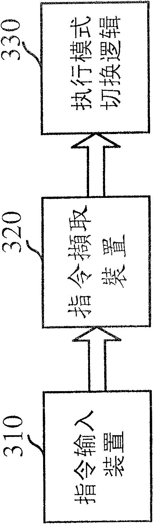
[0021] image 3 It shows the system architecture of the processor using parity check to switch the instruction mode of the present invention, which includes an instruction input device 310, an instruction fetch device 320 and an execution mode switching logic 330...


PUM


Abstract

The instruction mode switching method is for switching between N bit mode and 2N bit mode. Each N bit word block includes P parity bits and (N-P) bits of instruction code, parity bits of each instruction in N bit mode set the N bit word block in the first parity state while parity bits of each instruction in 2N bit mode set the N bit word block in the second parity state. The processor includes one instruction input device with 2N bit memory space for saving several 2N bit instruction word blocks, one instruction pick-up device for picking up one 2N word block from the instruction input device, and one execution mode switching logic for judging whether the picked 2N word block is either two (N-P) bit instructions or one 2(N-P) bit instruction.

Description

technical field [0001] The invention relates to the technical field of processors, in particular to a processor and a method for switching instruction modes by using parity check in a computer device. Background technique [0002] General processors have a 32-bit / 16-bit instruction mode, and switch between these two modes to save the space required for program code storage. , PC) to determine that the processor is in a 32-bit or 16-bit instruction mode, and use a branch (Branch) instruction to switch the value of the T bit in the program counter. The instruction mode switching is as follows figure 1 As shown, when the branch (Branch) instruction 220 is executed, it branches to (Branch to) the starting address Badd (1) stored in the 16-bit instruction and executes the 16-bit instruction. The +1 is used to switch the T bit To indicate that the processor is in the 16-bit instruction mode, when executing the branch (Branch) instruction 240, it is to branch to (Branch to) the ad...

Claims


Application Information

Patent Timeline
Patent Type & Authority Patents(China)
IPC IPC(8): G06F9/30G06F9/32
Inventor 梁伯嵩
Owner SUNPLUS TECH CO LTD
Why Eureka
Try Eureka