Magnetic conversion motor

A technology of engines and motors, applied in the direction of magnetic circuit rotating parts, electric components, electromechanical devices, etc., can solve problems such as failure to meet design requirements, and achieve the effects of good dynamic response, adjustable speed, and large speed range

Inactive Publication Date: 2007-07-25
高宗大
View PDF2 Cites 9 Cited by
  • Summary
  • Abstract
  • Description
  • Claims
  • Application Information

AI Technical Summary

Problems solved by technology

Although the efficiency of the motor is significantly improved compared with the existing motor, it does not meet the design requirements due to defects in the design

Method used


Image

  • Magnetic conversion motor
  • Magnetic conversion motor
  • Magnetic conversion motor

Examples


Embodiment Construction

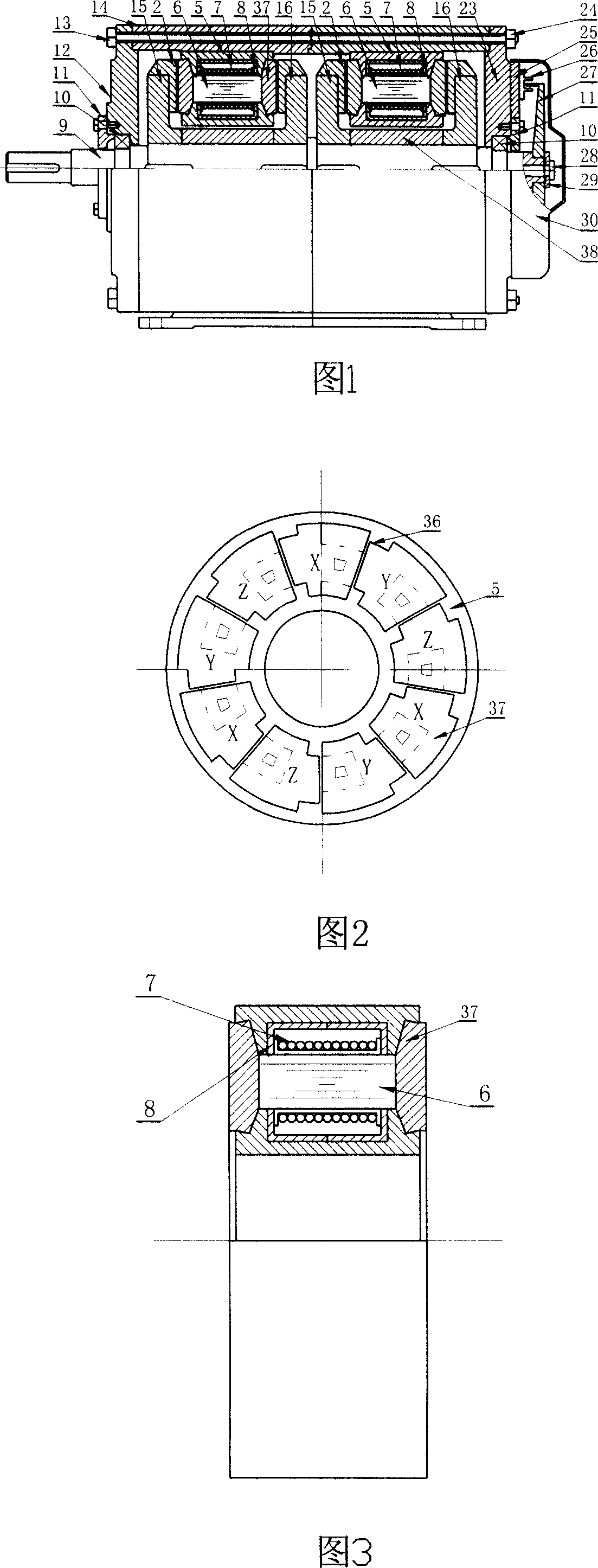
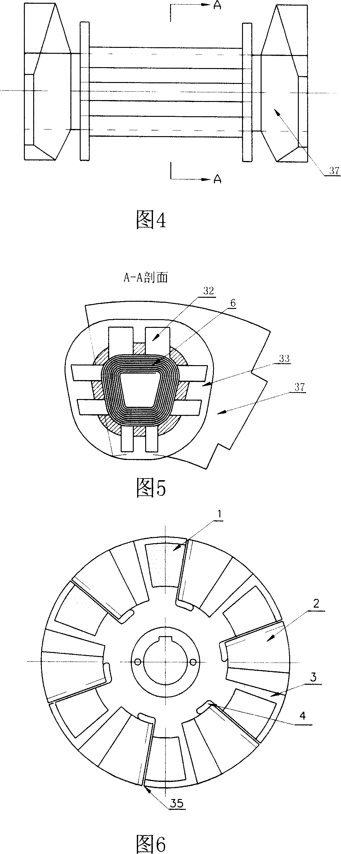
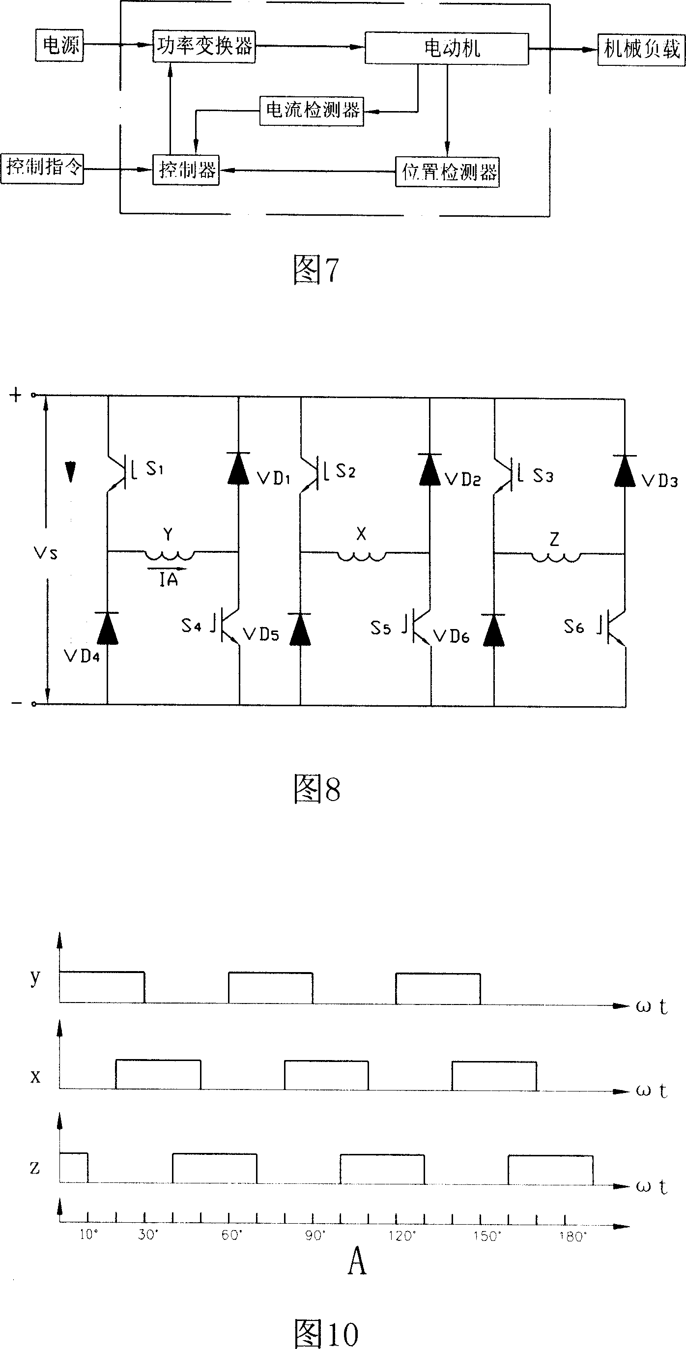
[0042] The overall structure of the magnetic conversion motor according to the present invention is shown in Figure 1, wherein 1 is a permanent magnet, 2 is a rotor soft magnetic pole, 3 is a rotor, 4 is a rotor gap, 5 is a stator, 6 is a winding core, 7 is Winding coil, 8 is an inner mold, 9 is a shaft, 10 a bearing, 11 is a bearing end cover, 12 is a left end cover, 13 is a bolt, 14 is a machine base, 15 is a left rotor, 16 is a right rotor, and 17 is a dividing plate, 18 is the generator stator winding, 19 is the generator stator, 20 is the generator rotor, 21 is the generator rotor winding, 22 is the slip ring, 23 is the right end cover, 24 is the nut, 25 is the photoelectric device fixing plate, 26 is the photoelectric Devices, 27 is the light chopper, 28 is the fastening bolt of the light chopper, 29 is the washer, 30 is the shield, 31 is the ventilation hole, 32 is the oil circuit, 33 is the winding frame, 34 is the commutator, 35 is the soft The gap between the magneti...


PUM


Abstract

Concretely, using kernel technique of electromotor, and changing structure of motor, the disclosed magnetic conversion engine forms a new type 'high efficiency and energy saving motor, becoming magnetic converted engine. Permanent magnet is installed on rotor of electromotor. Under action of magnetic field of electric current, permanent magnetic field builds up and magnifies magnetic field of torsion so as to increase mechanical efficiency of motor. Drive system of the motor is composed of power converter, controller, and position detector. Comparing with current brushless motor, and asynchronous motor, the disclosed motor possesses higher efficiency. Features are: small size, simple structure, electricity saving, adjustable rotation speed, broad usage, and satisfying specific load and application.

Description

technical field [0001] The invention relates to a motor, in particular to a magnetic conversion motor combining a motor and a generator, and belongs to the technical field of motors. Background technique [0002] The motor is an energy conversion device commonly used to realize the mutual conversion of electrical energy and mechanical energy, and has been widely used in every field of life and life. Since the development of modern motor technology for more than 100 years, the technology has become increasingly mature, and the types are constantly being introduced. In addition to traditional transformers, DC motors, synchronous AC motors, and asynchronous AC motors, stepping motors and reluctance motors have also been developed in recent years. Motors, linear motors and other new motors. [0003] At present, with the continuous enhancement of people's awareness of environmental protection, in order to protect the atmosphere from pollution, the development and popularization ...

Claims


Application Information

Patent Timeline
Patent Type & Authority Applications(China)
IPC IPC(8): H02K16/00H02K29/06H02K1/12H02K1/27H02K3/04H02K11/00H02K5/04H02K11/21H02K11/27
Inventor 高宗大
Owner 高宗大
Why Eureka
Try Eureka