Method and system for synchronizing time and frequency in orthogonal frequency division multiplex communication

A frequency synchronization and multiplexing communication technology, applied in the direction of multi-frequency code system, etc., can solve the problems of data detection interference, reduce system overhead, algorithm performance degradation, etc., achieve low overhead, achieve the effect of time and frequency synchronization

Inactive Publication Date: 2007-07-25
HUAWEI TECH CO LTD +1
0 Cites 73 Cited by

AI-Extracted Technical Summary

Problems solved by technology

[0018] The main disadvantage of the method of superimposing the PN sequence is: the power of the PN sequence limits the minimum value of the bit error rate, usually the transmission signal requires a bit error rate as low as possible, and time and frequency synchronization require the PN sequence to have a certain power, both Contradictory; the PN sequence is superimposed on the random data and can only be used for synchronization. To achieve the correct demodulation of the signal, additional overhead is required for channel estimation, etc.; the method is originally aimed at the SISO system. If it is directly applied to In the MIMO-OFDM system, each antenna needs to superimpose the training sequence. Under the objective condition of a certain total transmission power, the ratio of data power to the total power will be further reduced, resulting in more serious interference of the da...

Method used

[0192] The construction method of the above-mentioned objective function is to construct an objective function for each pair of transmitting and receiving antennas respectively, wherein the time synchronization of each transmitting antenna is realized based on suppressing other antenna data. When the number of transmitting antennas is large, the interference will increase and the performance will decrease. According to formula (38), the peak value of the objective function can be made larger by increasing K. Synchronization accuracy is also improved by reconstructing the synchronization function using the diversity gain as follows. The specific conditions are specifically described below.
[0213] It can be seen from the foregoing embodiments that in the present invention, by designing special pilot sequences of each transmitting antenna, the system can realize time and frequency synchronization with lower overhead, and each antenna only needs to send one in the frequency domai...

Abstract

In the invention, at transmitting terminal, the original information treated with carrier modulation is serial-parallel converted into several branch data streams whose amounts are identical with the amounts of antennas; the branch data streams and frequency-domain pilot frequency sequence are commonly mapped into the data position corresponding to the preset frequency-domain pilot frequency pattern; generating each antenna data information which is processed with OFDM modulation and is transmitted by RF transmission. At receiving terminal, each antenna receives the RF signals and generates time-domain output sequence the time-domain output sequence is correlated with the reference sequence to construct synchronous objective function between each pair of antennas so as to implement the synchronization between time and frequency.

Application Domain

Technology Topic

Rf transmissionCarrier signal +7

Image

  • Method and system for synchronizing time and frequency in orthogonal frequency division multiplex communication
  • Method and system for synchronizing time and frequency in orthogonal frequency division multiplex communication
  • Method and system for synchronizing time and frequency in orthogonal frequency division multiplex communication

Examples

  • Experimental program(1)

Example Embodiment

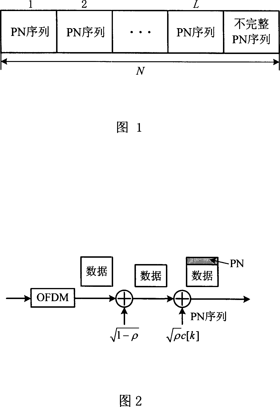
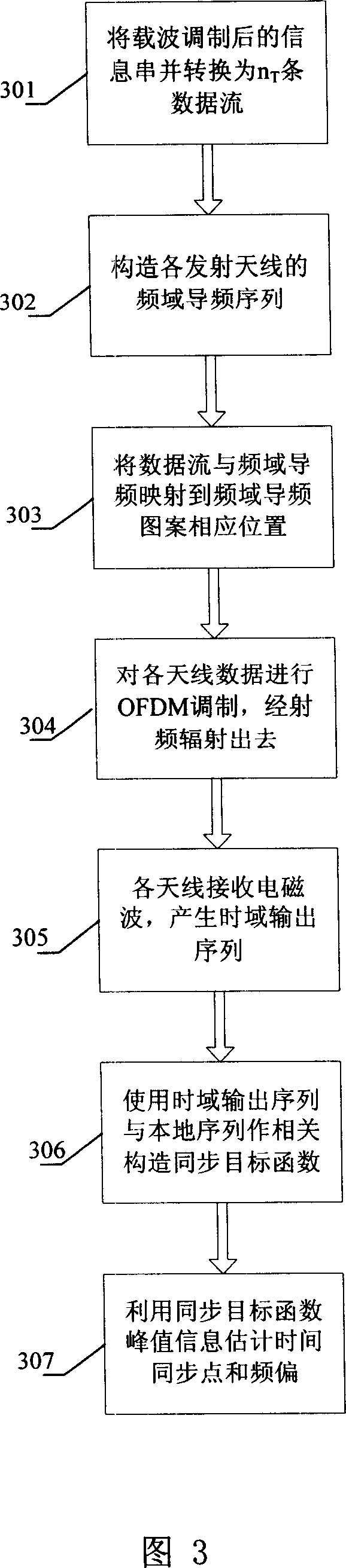
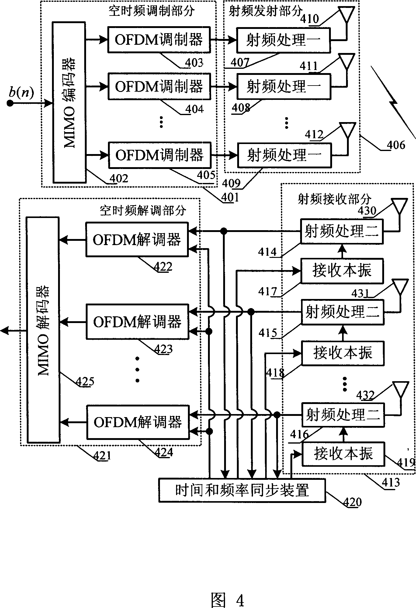
[0075] The method for time and frequency synchronization between a transmitted signal and a received signal in OFDM communication provided by the embodiment of the present invention can be used in a MIMO system. The method is a joint process including the transmission data structure at the transmitting end and the time and frequency synchronization using the transmission data with a specific structure at the receiving end. The idea is to use pilots in the communication process, design the frequency domain joint pilot pattern of each antenna at the transmitting end to make the time domain sequence have a specific correlation, and then use the time domain correlation to synchronize time and frequency.
[0076] The method and system for MIMO-OFDM time and frequency synchronization provided by the embodiments of the present invention will be described in detail below with reference to the accompanying drawings.
[0077] In a preferred embodiment of the present invention, the schematic flow chart of the MIMO-OFDM time and frequency synchronization method is shown in FIG. 3, where steps 301 to 304 are transmitter steps, and steps 305 to 307 are receiver steps.
[0078] First, in step 301, the original information string after carrier modulation is converted into n T Branch data stream, where n T Is the number of transmit antennas; then, step 302 constructs the frequency domain pilot sequence of each transmit antenna; then, in step 303, the branch data stream of each transmit antenna generated in step 301 is shared with the frequency domain pilot sequence constructed in step 302 Map to the corresponding data position of the predetermined frequency domain pilot pattern to generate the data information of each transmitting antenna; at the end of the transmitting end, step 304, the data information of each antenna is OFDM modulated and transmitted via radio frequency.
[0079] At the signal receiving end, first, in step 305, each receiving antenna receives electromagnetic waves to generate a time-domain output sequence; then, in step 306, according to the correlation between the time-domain output sequence and the local sequence, construct a time point between each pair of antennas Is the synchronization objective function of the independent variable; after that, in step 307, the time synchronization point and frequency offset are estimated using the peak information of the synchronization objective function.
[0080] It should be noted that there is no inheritance relationship between step 301 and step 302, and the order of the two can be arbitrary, that is, either one can be performed first, or both can be performed simultaneously and separately.
[0081] The OFDM communication time and frequency synchronization method of the embodiment of the present invention will be specifically implemented by being applied to an OFDM communication system. In a preferred embodiment of the present invention, the system principle block diagram of the MIMO-OFDM communication time and frequency synchronization method is shown in FIG. 4. The MIMO-OFDM communication system includes a space-time-frequency modulation part 401, a radio frequency transmitting part 406, a radio frequency receiving part 413, a time-frequency synchronization device 420, and a space-time frequency demodulation part 421.
[0082] The space-time-frequency modulation part 401 and the radio frequency transmitting part 406 are located at the transmitting end. The space-time-frequency modulation part 401 further includes: a multiple-input multiple-output encoder 402 for encoding the original input information, and generating data information for each antenna according to the frequency domain pilot pattern. The more specific internal structure of the MIMO encoder 402 will be It will be described in detail below in conjunction with Figure 6; multiple OFDM modulators (403, 404, 405) perform OFDM modulation for the data information of each antenna to generate OFDM symbols, where OFDM modulation can be achieved through IDFT (Inverse Discrete Fourier Transform, Inverse Discrete Fourier Transform) Transformation) implementation; RF transmission part, including multiple sets of radio frequency processing one (407, 408, 409) and the combination of transmitting antennas (410, 411, 412), each combination (such as the combination of radio frequency processing one 407 and transmitting antenna 410) Corresponding to an OFDM modulator, the OFDM symbol is processed by radio frequency processing and transmitted through the transmitting antenna.
[0083] The radio frequency receiving part 413, the time and frequency synchronization device 420, and the space-time frequency demodulation part 421 are located at the receiving end. The radio frequency receiving part 413 includes a combination of multiple groups of receiving antennas (430, 431, 432), receiving local oscillators (417, 418, 419) and radio frequency processing two (414, 415, 416), and each combination corresponds to an OFDM demodulator Each combination receives radio frequency signals through a receiving antenna, and performs radio frequency processing by radio frequency processing two according to the frequency information of the received local oscillator to generate a time domain output sequence of the received signal. The function of the time and frequency synchronization device 420 is to perform time and frequency synchronization. According to the correlation between the time-domain output sequence and the local sequence, construct a synchronization objective function with the time point as the independent variable between each pair of antennas, and use the peak information of the synchronization objective function The time synchronization point and frequency offset are estimated, and the specific method will be described in detail later in conjunction with FIG. 10. The time synchronization point and frequency offset information estimated by the time and frequency synchronization device 420 are transmitted to the receiving local oscillator (417, 418, 419) and the OFDM demodulator (422, 423, 424). The OFDM demodulator combines the estimated time synchronization point and frequency offset information to perform OFDM demodulation on the time domain output sequence of the received signal to obtain the restored data information of each antenna, of which the time synchronization point is mainly used. information. The multiple-input multiple-output decoder 425 first uses the frequency domain pilots in the restored data information of each antenna to estimate the pilot auxiliary channel, and then performs space-time-frequency decoding to obtain the restored original input information.
[0084] The working process and principle of some of the devices in Fig. 4 will be described in further detail below.
[0085] At the transmitting end, the function of the MIMO encoder 402 is to generate data information of each antenna according to the frequency domain pilot pattern. FIG. 5 is a schematic diagram of an embodiment of a frequency domain pilot pattern jointly designed by each antenna in a preferred embodiment of the present invention. In the figure, the horizontal axis is each antenna, and the vertical axis corresponds to each subcarrier. It can be seen from Figure 5 that each antenna adopts a pilot-assisted OFDM (Pilot-Assisted OFDM) transmission structure, and frequency-domain pilots are placed at equally spaced sub-carrier positions (the sub-carriers are called pilot sub-carriers). The positions of the pilot sub-carriers of each antenna are different from each other, and the data information is loaded at a position outside the frequency band containing the pilot sub-carriers. If the number of OFDM subcarriers is N, the pilot subcarrier is N p , Then the data position of each antenna is (N-n T N p ) Subcarriers. The spacing between the pilot sub-carriers of each antenna is D f , Obviously D f It should be at least greater than the total number of antennas.
[0086] The composition and mapping methods of pilots and data in the frequency domain pilot patterns are introduced below. First introduce the structure of the pilot sequence. The i-th transmitting antenna, i=1, 2, K n T The method for constructing the pilot sequence contained in an OFDM symbol is as follows: select multiple segments with better correlation as the basic sequence; repeat the selected multiple segments of the basic sequence, and multiply each segment of the basic sequence by the corresponding coefficient to form the time domain pilot Frequency sequence; Discrete Fourier transform is performed on the time domain pilot sequence to obtain the frequency domain pilot sequence.
[0087] The purpose of adopting this construction method is to make the frequency domain pilot frequency meet the predetermined pilot frequency pattern and have good correlation. The construction principle and specific content of the frequency domain pilot frequency sequence are explained below.
[0088] Starting from the frequency domain, suppose the number of DFT points is N, the pilot subcarrier spacing of each antenna is M, and it is required that M can divide N evenly. In order to use the FFT (Fast Fourier Transform, Fast Fourier Transform) method to calculate DFT, the number of DFT points N is generally required to be 2 n , So the condition that M divides N is easily satisfied. Frequency domain pilot X of the i antenna i Can be expressed as an impulse string
[0089] X i ( k ) = Σ r = 0 N M - 1 α r i δ ( k - Mr - p i ) , k = 0 , K , N - 1 ; i = 1 , K , n T - - - ( 16 )
[0090] Where p i Represents the shift of the position of the first pilot subcarrier of the i-th transmitting antenna relative to k=0, p i = 0, 1, K M-1, a r i Represents the rth pilot symbol of the i-th transmitting antenna. The pilot frequencies of different antennas should be staggered, so p i Must be different, so this pilot configuration method requires n T ≤M.
[0091] X i (k) The corresponding N-point time-domain sequence after IDFT is:
[0092] x i ( n ) = e j 2 π N p i n Σ r = 0 N M - 1 α r i e j 2 π N Mnr - - - ( 17 )
[0093] It can be seen that the time domain sequence has the following quasi-periodic characteristics: for p i =0, the time domain sequence obviously takes N/M as the period; for p i =1, K, M-1, the time domain sequence has no periodicity, but the entire sequence can be regarded as repeating the first N/M points of the sequence M times, and each segment is multiplied by
[0094] α = [ 1 , e j 2 π M p i , e j 2 π M ( 2 p i ) , K , e j 2 π M ( ( M - 1 ) p i ) ] - - - ( 18 )
[0095] When p i =0, the conclusion is also established, at this time formula (18) is α=[1,...,1].
[0096] The N-point sequence corresponding to the frequency domain pilot sequence after IDFT is called the time domain pilot sequence. Both are frequency domain and time domain representations of the same mathematical entity sequence.
[0097] According to the time-domain characteristics of the frequency-domain pilot sequence, N-point pilot sequences can be directly generated in the time domain, so that PN sequences with better correlation characteristics can be selected to improve the performance of time and frequency synchronization. The steps to directly generate the pilot sequence in the time domain are:
[0098] Each transmitting antenna time-domain sequence generator generates a PN sequence c with a length of K=N/M points i , I=1, K, n T. The basic sequence requires the PN sequence of each antenna c i The cross-correlation characteristics are good. Will c i Repeat M times to get the same PN sequence of M segments, and multiply each segment by the corresponding α t i , T=0, K, M-1, which constitute the N-point time-domain pilot sequence x of antenna i i (n).
[0099] Generally, as a requirement for separation and design, a cyclic prefix is ​​added before the pilot sequence. FIG. 6 is a schematic diagram of a time domain pilot sequence containing a cyclic prefix in a preferred embodiment of the present invention. Figure c q α t q Represents the t-th segment of the time-domain pilot sequence of the q-th transmitting antenna. Where α t i defined as
[0100] α t i = e j 2 πt M p i , t = 0 , K , M - 1 , i = 1 , K , n T - - - ( 19 )
[0101] Put these parameters into formula (17) to form x i (n), obviously its DFT form X i (k) is the form of impulse series distributed at equal intervals, when used as a pilot, different antennas are X i (k) Staggered.
[0102] Next, the mapping method of data in the frequency domain pilot pattern is explained: For a certain antenna, the number of pilot subcarriers is N p =N/M, the pilot frequencies of all antennas occupy n T N p Sub-carriers, so the data symbols of each antenna are mapped to the remaining N-n T N p =N(1-n T /M) data subcarriers. In this way, the pilot and data do not overlap in the frequency domain.
[0103] The structure of the MIMO encoder 402 in FIG. 4 will be described in detail below in conjunction with the generation of the pilot sequence, the setting of the predetermined pilot pattern, and the data mapping method. The principle block diagram of the MIMO encoder 402 is shown in FIG. 7, which includes a modulator 726, a serial-to-parallel conversion device 727, and a pilot mapping part.
[0104] The modulator 726 performs carrier modulation on the original input information, such as BPSK (Binary Phase Shift Keying, binary phase shift keying) modulation to generate a modulated data stream; a serial-to-parallel conversion device 727 converts the carrier-modulated data stream serially to parallel N T Branch data stream, n T Is the number of transmitting antennas; the pilot mapping part constructs the frequency domain pilot sequence of each transmitting antenna, and maps the branch data stream and frequency domain pilot sequence of each transmitting antenna to the corresponding data position of the predetermined frequency domain pilot pattern to generate Data information of each transmitting antenna. The specific working mode of the pilot mapping part is to flow the data of each branch through the serial-to-parallel conversion device 728, 729 and then convert the serial-to-parallel to N-n again. T N p It is mapped to the corresponding data position of the frequency-domain pilot pattern through the mapping devices 732, 733. Obviously the data will occupy the N-n of the subcarrier. T N p Data positions; the pilot sequence generating devices 730, 731 generate a time domain pilot sequence corresponding to each antenna, and the DFT device 734, 735 transforms it into a frequency domain pilot sequence. The frequency domain pilot of each antenna will occupy N p Data locations. It should be noted that the pilot sequence generating device may include an appropriate circuit, logic, or processor, which generates a time-domain pilot sequence through appropriate circuit or logical connection or execution of an appropriate program. After the frequency domain pilot sequence is obtained, the frequency domain pilot sequence and the mapping data are synthesized by the synthesis devices 736 and 737 to generate data information for each transmitting antenna.
[0105] It should be noted that in FIG. 6, as an example, only the respective devices corresponding to the two antennas are marked, but such marking should not be used as a limitation to the present invention. As shown in the ellipsis part between the two antennas in Figure 6, the number of transmitting antennas is n T It can be any natural number. Obviously, a single transmitting antenna as a special case will also fall into the protection scope of the present invention.
[0106] After generating the data information of each transmitting antenna, multiple OFDM modulators (403, 404, 405) perform OFDM modulation on the data information of each antenna to generate OFDM symbols, where OFDM modulation can be implemented by IDFT. After the data mapping is completed, a preferred way is to add a prefix to generate OFDM symbols. The lth OFDM symbol transmitted by the i-th transmitting antenna can be regarded as the sum of the pilot and data parts, add N g The transmitted signal after the dotted cyclic prefix can be expressed as
[0107] s i l ( n ) = d i l ( n ) + x i l ( n ) , n = 0 , K , N + N g - 1 , i = K , n T - - - ( 20 )
[0108] Where d l i (n) and x l i (n) respectively represent the nth sample value of the time domain of the data sequence and the pilot sequence contained in the lth OFDM symbol of the i-th transmit antenna.
[0109] The block diagram of the OFDM modulator is shown in Figure 8. Since OFDM modulation can be realized by IDFT, the OFDM modulator includes an IDFT device and a device for adding a cyclic prefix.
[0110] The OFDM symbols generated by the modulation are sent to the radio frequency transmitting part. The transmitting part includes multiple sets of radio frequency processing one (407, 408, 409) and the combination of transmitting antennas (410, 411, 412), each combination (such as radio frequency processing one 407 and The combination of the transmitting antenna 410) corresponds to an OFDM modulator, and the OFDM symbols are subjected to radio frequency processing by radio frequency processing and transmitted through the transmitting antenna.
[0111] Among them, the first radio frequency processing is a radio frequency transmitter, and FIG. 9 is a functional block diagram of the radio frequency transmitter in a preferred embodiment of the present invention. It includes transmitting local oscillator, filter one and amplifier one. The input signal and the transmitting local oscillator are synthesized, filtered by the first filter, and amplified by the first amplifier to generate the transmitted signal.
[0112] The transmitted signal cannot reach the receiving end until it travels a certain distance in space. There is a complex channel space between the signal transmitting end and the receiving end. Modeling the channel space is the basis of using the received signal and the local sequence to form a synchronization function. For example, the channel between the transmitting antenna i and the receiving antenna j can be a quasi-static frequency-selective non-coherent scattered Rayleigh fading channel, that is, the channel changes randomly at the beginning of each OFDM symbol, but in an OFDM symbol Stay the same over time. Assuming that the channel has L channel impulse responses with different delays, the tapped delay line model is adopted, and the channel impulse response can be expressed as:
[0113] h j , i l ( τ ) = Σ m = 0 L - 1 h j , i % ( m ) δ ( τ - τ m ) - - - ( 21 )
[0114] Where h j,i l (τ) represents the impulse response of the multipath channel between the transmitting antenna i and the receiving antenna j within the l-th OFDM symbol time, L is the number of channel multipaths, Represents the equivalent low-pass impulse response of the m-th path of the multipath channel between the transmitting antenna i and the receiving antenna j within the l-th OFDM symbol time, t m Represents the time delay of the m-th path.
[0115] The sending signal can be expressed as a (n T (N+N g ))×1 column vector S l
[0116] S l = ( s 1 l ( 0 ) M S n T l T , s 1 l ( 1 ) M s n T l ( 1 ) T , K , s 1 l ( N + N g - 1 ) M s n T l ( N + N g - 1 ) T ) T - - - ( 22 )
[0117] Among them, (g) T Represents transpose operation, s i l (n) represents the nth sample value in the time domain of the i-th transmitting antenna transmitting the OFDM symbol at the lth OFDM symbol time.
[0118] The channel impulse response model shown in equation (21) can be expressed in the form of a time-varying FIR (Finite Impulse Response, finite-length impulse response) filter, so n T Transmitting antenna n R The multiple-input multiple-output channel model of a receiving antenna can be expressed as (n R (N+N g +N L -1))×(n T (N+N g )) matrix H l , Where N L Represents the number of delayed sampling points of the L-th path,
[0119] H l = H ( 0 ) 0 L 0 H ( 1 ) H ( 0 ) L M M H ( 1 ) L 0 H ( N L - 1 ) M L H ( 0 ) 0 H ( N L - 1 ) L H ( 1 ) M M L M 0 0 L H ( N L - 1 ) - - - ( 23 )
[0120] among them,
[0121] H ( m ) = h 1,1 l ( m ) K h 1 , n T l ( m ) M O M h n R , 1 l ( m ) L h n R , n T l ( m ) , m = 0 , . . . , N L - 1 - - - ( 24 )
[0122] Consider the additive complex Gaussian white noise, and receive the signal R when the time and frequency are completely synchronized l Can be expressed as (n R (N+N g +N L -1))×1 column vector
[0123] R l =H l S l +W l (25)
[0124] Where W l The elements of are zero-mean additive white Gaussian noise samples, and the variance is σ w 2 , Can be expressed as
[0125] W l = ( w 1 l ( 0 ) M w n R l ( 0 ) , T w 1 l ( 1 ) M w n R l ( 1 ) T , K , w 1 l ( N + N g + N L - 2 ) M w n R l ( N + N g + N L - 2 ) T ) T - - - ( 26 )
[0126] After the signal propagates through the channel, it reaches the receiving end from the sending end. At the receiving end, the radio frequency receiving part 413 first receives electromagnetic waves to generate a time-domain output sequence. The radio frequency receiving part 413 includes a combination of multiple groups of receiving antennas (430, 431, 432), receiving local oscillators (417, 418, 419) and radio frequency processing two (414, 415, 416), and each combination corresponds to an OFDM demodulator Each combination receives radio frequency signals through a receiving antenna, and performs radio frequency processing by radio frequency processing two according to the frequency information of the received local oscillator to generate a time domain output sequence of the received signal.
[0127] The second radio frequency processing is the radio frequency receiver. Fig. 11 is a functional block diagram of a radio frequency receiver in a preferred embodiment of the present invention. The input signal is first amplified by the amplifier, and then filtered by the second filter. The filtered signal is combined with the signal from the receiving local oscillator, and the synthesized signal is filtered by the filter again to obtain the output of the radio frequency receiver.
[0128] Next, the time and frequency synchronization device 420 performs time and frequency synchronization. According to the correlation between the time-domain output sequence and the reference sequence, a synchronization objective function with the time point as the independent variable between each pair of antennas is constructed, and the peak information of the synchronization objective function is used Estimate the time synchronization point and frequency offset. The working principle of the time and frequency synchronization device 420 will be described in detail below.
[0129] When the time and frequency are completely synchronized, from formula (22) to formula (26), the received signal of the j-th receiving antenna at the l-th symbol time can be expressed as
[0130] r j l ( n ) = Σ i = 1 n T Σ m = 0 L - 1 h j , i l ( m ) s i l ( n - m ) + w j l ( n ) , n = 0 , K , N + N g - 1 - - - ( 27 )
[0131] Since l and n are both time variables, there are r j l ( n ) = r j ( n + l ( N + N g ) ) . For the convenience of expression, let n′=n+l(N+N g ), so n'is the sequence number of the actual OFDM symbol time domain sampling point: n'=0,1,K.
[0132] Considering the time delay and frequency offset, let the receiving delay of the j-th receiving antenna to the i-th transmitting antenna be θ j,i , Suppose the normalized frequency deviation of the radio frequency receiver is ε j,i , I=1,...,n T , J=1,...,n R. The received signal of the j-th receiving antenna can be expressed as
[0133] r j ( n ′ ) = Σ i = 1 n T Σ m = 0 N L - 1 h j , i l ( m ) s i ( n ′ - m - θ j , i ) e j 2 πϵ j , i n ′ / N + w j ( n ′ )
[0134]
[0135] Among them, g means rounding down.
[0136] In the following, the synchronization between the j-th receiving antenna and the q-th transmitting antenna is taken as an example to describe the specific synchronization algorithm, and the methods between other pairs of antennas are similar. From formula (28), we can get
[0137] r j ( n ′ ) = Σ m = 0 N L - 1 h j , q l ( m ) s q ( n ′ - m - θ j , q ) e j 2 πϵ j , q n ′ / N
[0138] + Σ i = 1 i ≠ q n T Σ m = 0 N L - 1 h j , i l ( m ) s i ( n ′ - m - θ j , i ) e j 2 πϵ j , i n ′ / N + w j ( n ′ )
[0139] = h j , q l ( m max ) s q ( n ′ - m max - θ j , q ) e j 2 πϵ j , q n ′ / N - - - ( 29 )
[0140] + Σ m = 0 m ≠ m max N L - 1 h j , q l ( m ) s q ( n ′ - m - θ j , q ) e j 2 πϵ j , q n ′ / N
[0141] + Σ i = 1 i ≠ q n T Σ m = 0 N L h j , i l ( m ) s i ( n ′ - m - θ j , i ) e j 2 πϵ j , i n ′ / N + w j ( n ′ )
[0142] Where m max It is the strongest path delay of the multipath channel between the transmitting antenna q and the receiving antenna j of the l OFDM symbol time. The strongest path is defined as m max = arg max m { E [ | h j , q l ( m ) | 2 ] } , E[g] means seeking mathematical expectation. Substitute formula (20) into formula (29), r j (n′) can be further expressed as
[0143] r j ( n ′ ) = h j , q l ( m max ) x q ( n ′ - m max - θ j , q ) e j 2 πϵ j , q n ′ / N - - - ( 30 )
[0144] + I Data + I ISI + I OtherAntenna + w j ( n ′ )
[0145] among them,
[0146] I Data = h j , q l ( m max ) d q ( n ′ - m max - θ j , q ) e j 2 πϵ j , q n ′ / N
[0147] I ISI = Σ m = 0 m ≠ m max N L - 1 h j , q l ( m ) s q ( n ′ - m - θ j , q ) e j 2 πϵ j , q n ′ / N - - - ( 31 )
[0148] I OtherAntenna = Σ i = 0 i ≠ q n T Σ m = 0 N L - 1 h j , i l ( m ) s i ( n ′ - m - θ j , i ) e j 2 πϵ j , q n ′ / N
[0149] I Data Represents the interference of the data with the strongest path of the qth transmitting antenna to the pilot signal, I ISI Indicates the interference of the other paths of the qth transmitting antenna to the strongest path signal. I Other Antenna Indicates the interference of other transmitting antennas to the qth transmitting antenna. Make w j % ( n ′ ) = I Data + I ISI + I OtherAntenna + w j ( n ′ ) , then r j (n′) can be expressed as
[0150] r j ( n ′ ) = h j , q l ( m max ) x q ( n ′ - m max - θ j , q ) e j 2 πϵ j , q n ′ / N + w j % ( n ′ ) - - - ( 32 )
[0151] According to the previous description of the pilot sequence in conjunction with Figure 6, x q l (n) The part except the cyclic prefix has a quasi-periodic nature, c q α t q Represents the t-th segment of the time-domain pilot sequence of the qth antenna, t=0, K, M-1. Where c q Is the PN sequence of the qth transmitting antenna, with a length of N/M. Let K=N/M, then x q l (n) can be expressed as
[0152]
[0153] A sliding window of length N is set for the qth transmitting antenna, and the variable n′ changes continuously with time to construct:
[0154] λ j , q ( n ′ ) = Σ t = 0 M - 1 [ ( Σ k = 0 K - 1 ( α t q ) * c q * ( k ) r j ( n ′ + k + tK ) ) - - - ( 34 )
[0155] · ( Σ k = 0 K - 1 ( α t + 1 q ) * c q * ( k ) r j ( n ′ + k + ( t + 1 ) K ) ) * ]
[0156] Let η j,q (n′)=|λ j,q (n′)|, then ηj,q (n') is the synchronization objective function.
[0157] With the synchronization objective function, the peak information of the synchronization objective function can be used to estimate the time synchronization point and frequency offset. One of the most direct methods to determine the correlation peak of the synchronization objective function is to set a threshold. When the objective function value exceeds the threshold, it is judged to be synchronized, and the corresponding sampling point is the time synchronization point.
[0158] The threshold is generated by an adaptive threshold method. The method is to synchronize the current output value of the objective function with the previous N 1 Point mean T h Double comparison, when it is greater than or equal to time synchronization, the judgment condition is as follows:
[0159] | λ j , q ( n ′ ) | ≥ T h Σ i = 1 N 1 | λ j , q ( n ′ - i ) | N 1 - - - ( 35 )
[0160] When the time synchronization is accurately completed, the objective function η j,q (n') The maximum peak should appear. For the first OFDM symbol, the peak value should be at n′=m max +θ j,q +N g When appearing. From formula (32) and formula (34),
[0161] at this time
[0162] λ j , q ( m max + θ j , q + N g )
[0163] = Σ t = 0 M - 1 [ ( Σ k = 0 K - 1 ( α t q ) * c q * ( k ) r j ( m max + θ j , q + N g + k + tK ) )
[0164] . ( Σ k = 0 K - 1 ( α t + 1 q ) * c q * ( k ) r j ( m max + θ j , q + N g + k + ( t + 1 ) K ) ) * ]
[0165] = Σ t = 0 M - 1 [ ( Σ k = 0 K - 1 ( α t q ) * c q * ( k ) ( h j , q l ( m max ) x q ( N g + k + tK ) e j 2 πϵ j , q ( m max + θ j , q + N g + tK ) / N - - - ( 36 )
[0166] + w j % ( m max + θ j , q + N g + k + tK ) ) )
[0167] . ( Σ k = 0 K - 1 ( α t + 1 q ) * c q * ( k ) ( h j , q l ( m max ) x q ( N g + k + ( t + 1 ) K ) e j 2 πϵ j , q ( m max + θ j , q + N g + k + ( t + 1 ) K ) / N
[0168] + w j % ( m max + θ j , q + N g + k + ( t + 1 ) K ) ) ) * ]
[0169] Due to x q ( n ′ ) = x q l ( n ′ - l ( N + N g ) ) , Using formula (33), the above formula can be simplified to
[0170] λ j , q ( m max + θ j , q + N g ) = | h j , q l ( m max ) | 2 Me - j 2 πϵ j , q K / N | sin ( πϵ j , q K / N ) sin ( πϵ j , q / N ) | 2 + w j ′ - - - ( 37 )
[0171] Where w j 'Is the sum of all additive irrelevant terms. It can be seen that formula (37) has a peak output during precise synchronization. According to the principle of spread spectrum, the modulus of the first term of formula (37) is much larger than that of the second term, so the interference term is ignored. Therefore, at the time of precise synchronization, The synchronization objective function value is:
[0172] η j , q ( m max + θ j , q + N g ) = | λ j , q ( m max + θ j , q + N g ) |
[0173] = | h j , q l ( m max ) | 2 M | sin ( πϵ j , q K / N ) sin ( πϵ j , q / N ) | 2 - - - ( 38 )
[0174] ≈ | h j , q l ( m max ) | 2 K 2 M | sin c ( πϵ j , q K N ) | 2
[0175] It can be seen that the objective function is related to the normalized frequency offset ε and the strongest path fading. For example, if N=1024 and K=128, the first zero point of the objective function changing with ε is obtained at ε=8. In the new generation of mobile communications, the carrier frequency is usually 3~3.5GHz. If the carrier frequency is 3.5GHz, the stability factor of the receiver crystal oscillator is 10ppm (one millionth), and the OFDM subcarrier interval is 20KHz, then ε= 1.75. At this time, as long as the strongest path does not undergo deep fading, the peak value of the time synchronization objective function is still high, which meets the requirements of time synchronization.
[0176] Since the received signal is quasi-periodic, the objective function η can be seen from formula (32), formula (33) and formula (34) j,q (n′) There are multiple peaks, which requires the threshold setting to be quite accurate, otherwise the simple threshold determination method will easily synchronize to the side lobe. In order to obtain an accurate synchronization point, the method needs to be improved and a search window is set. The steps of the improved method are as follows: First, find the n that satisfies the formula (35) 1 'Point; in the interval Search in η j,q (n′) maximum point n 2 ′; point n 2 'Is the corresponding synchronization point (synchronized to the strongest path).
[0177] This improved method achieves synchronization of the strongest path, but the strongest path may not be the first path, although the strongest path is usually the first path. Due to the cyclic prefix, the demodulation of OFDM does not need to be strictly synchronized to the first path. However, if the first path cannot be synchronized, the multipath energy before the strongest path will not only be unavailable, but will also interfere with signal demodulation. For this reason, a preferred embodiment of the present invention provides the following method for synchronization of the first path: first find the strongest path; 2 Point to start searching backward; set the judgment to be tortured as the objective function than the previous N 3 Point mean N 4 Doubled; find the point that meets the judgment condition is the first path, otherwise the strongest path is the first path.
[0178] This is done because even if there is a multipath component before the strongest path, the objective function value corresponding to its gain does not satisfy the determination condition, indicating that its gain is much smaller than the strongest path and can be ignored.
[0179] Assume that the time synchronization of each antenna has been completed. It can be seen from (37) that ε j,q The following methods can be used to estimate:
[0180] ϵ ^ j , q = N 2 πK · arg ( λ j , q ( m max + θ j , q + N g ) ) - - - ( 39 )
[0181] Among them, arg(g) is the calculation of the phase angle.
[0182] According to the above-mentioned time and frequency synchronization method, in a preferred embodiment of the present invention, a schematic diagram of a module of a synchronization algorithm embodiment of the time and frequency synchronization device 420 is shown in FIG. 10. Among them, module 1038, module 1039, module 1040, and module 1041 are used to construct λ in formula (34) j,q (n′), module 1042 pairs λ j,q (n′) Take the absolute value to obtain the synchronization objective function|λ i (k)|. After that, the module 1043 is used according to the known |λ i (k)|Calculate the decision threshold, and then the comparison module judges according to formula (35), finds the peak of the synchronization objective function, and initially determines the synchronization point. After the synchronization point is initially determined, the module 1045 is further used to find the first path between the antennas. At the same time, the module 1046 takes the phase angle of the peak value of the synchronization objective function to obtain the frequency offset estimation value.
[0183] The synchronization method of the embodiment of the present invention can realize the integer part frequency offset estimation and the fractional part frequency offset estimation at the same time. The frequency offset estimation range is | ϵ ^ | ≤ N 2 K . Set N=1024, K=128, then | ϵ ^ | ≤ 4 . Assuming that the carrier frequency is 3.5GHz, the stability coefficient of the receiver crystal oscillator is 10ppm (one millionth), and the OFDM subcarrier spacing is 20KHz, then ε=1.75<4, indicating that the frequency synchronization of the present invention can meet the requirements of the new generation of mobile communications Frequency synchronization requirements.
[0184]In the time and frequency synchronization process, the method of transmitting and receiving diversity can be used to improve the accuracy of the frequency synchronization algorithm. For a MIMO system with the same frequency offset between each pair of transmitting and receiving antennas, there are
[0185] ϵ ^ = - N 2 πK · arg ( Σ q = 1 n T Σ j = 1 n R λ j , q ( m max + θ j , q + N g ) ) - - - ( 40 )
[0186] After the first frequency synchronization, there will still be residual frequency offset due to the influence of interference, which can be achieved by the second frequency synchronization. Assuming that the first frequency synchronization can completely cancel the integer part of the frequency offset, the residual frequency offset can be achieved by using the farther data to do another frequency offset estimation after the receiver compensates it. Rewrite formula (34) as
[0187] λ j , q ( n ′ ) = Σ t = 0 M - P - 1 [ ( Σ k = 0 K - 1 ( α t q ) * c q * ( k ) r j ( n ′ + k + tK ) )
[0188] . ( Σ k = 0 K - 1 ( α t + 1 q ) * c q * ( k ) r j ( n ′ + k + ( t + P ) K ) ) * ] - - - ( 41 )
[0189] It can be derived using a method similar to the first frequency offset estimation Calculation formula:
[0190] ϵ ^ j , q = - N 2 πPK · arg ( λ j , q ( m max + θ j , q + N g ) ) - - - ( 42 )
[0191] Among them, P is used to adjust the accuracy. The larger the P, the higher the accuracy, but the smaller the frequency offset estimation range. So It can be expressed as a sum of two parts: ϵ ^ j , q = ϵ ^ j , q 1 + ϵ ^ j , q 2 , with Represent the results of the first and second frequency offset estimation respectively.
[0192] The above method for constructing the objective function is to construct the objective function separately for each pair of transmitting and receiving antennas, wherein the time synchronization of each transmitting antenna is realized based on the suppression of other antenna data. When the number of transmitting antennas is large, the interference will increase and the performance will decrease. It is known from formula (38) that the peak value of the objective function can be made larger by increasing K. The synchronization accuracy is also improved by reconstructing the synchronization function using the following diversity gain. The specific conditions are described in detail below.
[0193] For example, when the delay from the same transmitting antenna to each receiving antenna is the same, receive diversity can be used. At this time, the synchronization objective function of the qth transmitting antenna is:
[0194] η q ( n ′ ) = | Σ j = 1 n R λ j , q ( n ′ ) | - - - ( 43 )
[0195] Similarly, when the delays from each transmitting antenna to the j-th receiving antenna are the same, transmit diversity can be used. At this time, the synchronization objective function of the j-th receiving antenna is:
[0196] η j ( n ′ ) = | Σ q = 1 n T λ j , q ( n ′ ) | - - - ( 44 )
[0197] When the time delay from each transmitting antenna to each receiving antenna is the same, and the frequency offset between each pair of transmitting and receiving antennas is the same, the transmit diversity can be further used, and the synchronization objective function is:
[0198] η ( n ′ ) = | Σ q = 1 n T Σ j = 1 n R λ j , q ( n ′ ) | - - - ( 45 )
[0199] In particular, for a MIMO system with the same frequency offset between each pair of transmitting and receiving antennas, if N is an even number, there is another method for frequency synchronization:
[0200] It can be seen from formula (18) that the N-point time-domain pilot sequence has the following properties: when p i When it is an odd number, the first N/2 points of the time-domain pilot sequence are equal to the last N/2 points multiplied by -1; when p i When it is an even number, the first N/2 points and the last N/2 points of the time-domain pilot sequence are the same.
[0201] The number of transmitting antennas is limited by the pilot sub-carrier spacing M. In theory, the number of transmitting antennas is n T ≤M, when n T = M no more data sub-carriers, in order not to reduce the spectrum utilization, it is required to meet at least n T ≤M/2.
[0202] Therefore, the displacement of the first pilot subcarrier position of the transmitting antenna in the predetermined pilot pattern relative to the origin of the OFDM subcarrier, that is, the pilot subcarrier position p of the i-th antenna i Set of i=0,...,n T -1, you can choose one of the following two sets:
[0203] p i ∈{0, 2,..., M-2} or p i ∈{1, 3,..., M-1} (46)
[0204] Namely: p i Must be all odd or all even.
[0205] Let the time synchronization point be n 1 ′, assuming that the time synchronization of each antenna has been completed, the frequency offset calculation formula is:
[0206] ϵ ^ = - N 2 πKM / 2 arg ( Σ t = 0 M / 2 - 1 Σ k = 0 K - 1 ( - 1 ) f r ( n 1 ′ + k + tK ) r * ( n 1 ′ + k + ( t + M / 2 ) K ) ) - - - ( 47 )
[0207] among them,
[0208] Equation (46) can be further written as
[0209] ϵ ^ = - 1 π arg ( Σ k = 0 N / 2 - 1 ( - 1 ) f r ( n ′ 1 + k ) r * ( n ′ 1 + k + N / 2 ) ) - - - ( 48 )
[0210] This method fully utilizes the diversity gain. The more the number of transmitting antennas, the more accurate the synchronization. The frequency offset estimation range is | ϵ ^ | ≤ 1 .
[0211] After obtaining the time synchronization point and frequency offset information, the time synchronization point and frequency offset information estimated by the time and frequency synchronization device 420 are transmitted to the receiving local oscillator (417,418,419) and the OFDM demodulator (422,423, 424). The OFDM demodulator combines the estimated time synchronization point and frequency offset information to perform OFDM demodulation on the time-domain output sequence of the received signal to obtain restored data information of each antenna. After that, the multiple-input multiple-output decoder 425 first uses the frequency domain pilots in the restored data information of each antenna to perform pilot auxiliary channel estimation, and then performs space-time-frequency decoding to obtain the restored original input information.
[0212] In a preferred embodiment of the present invention, the principle block diagram of the OFDM demodulator is shown in FIG. 12. Corresponding to the OFDM modulator in Figure 8, the OFDM demodulator in Figure 12 includes a cyclic prefix removal module and a DFT module. The input signal is first removed from the cyclic prefix and then DFT is performed to generate the output signal.
[0213] As can be seen from the foregoing embodiments, in the present invention, by designing special pilot sequences of each transmitting antenna, the system can achieve time and frequency synchronization with lower overhead. Each antenna only needs to send one pilot inserted in the frequency domain. For OFDM symbols, no additional training sequence is needed, and the synchronization task can be completed while the MIMO channel estimation and the transmission of the bearer data service can be completed. The time and frequency synchronization method is suitable for complex actual MIMO systems. The time delay from each transmitting antenna to each receiving antenna can be different, and the frequency offset between each pair of transmitting and receiving antennas can also be different. At the same time, the diversity gain of the antenna can be used to further improve the synchronization performance. Compared with the traditional synchronization method in which only the strongest path can be captured, the embodiment of the present invention provides a method for capturing the first path. At the same time, compared with the existing method, the present invention also has the advantages of being suitable for multipath channels and no need to estimate the signal-to-noise ratio.
[0214] It should be noted that in the process of describing the specific implementation of the present invention in conjunction with FIG. 4, as an example, the radio frequency processing one, radio frequency processing two, OFDM modulator, OFDM demodulator, receiving local oscillator and other devices of each link are only It shows a certain number (for example, only two transmitters 602, 603 are marked), but such marking is not a limitation to the scope of the present invention. The scope of the present invention will include all combinations of the number of transmitting antennas and receiving antennas that meet the conditions of the present invention. In particular, the case of a single-input antenna or a single-output antenna is a special case of the present invention. The methods and systems involved in various aspects of the present invention are fully applicable to the situation, and therefore will also fall within the protection scope of the present invention.

PUM

no PUM

Description & Claims & Application Information

We can also present the details of the Description, Claims and Application information to help users get a comprehensive understanding of the technical details of the patent, such as background art, summary of invention, brief description of drawings, description of embodiments, and other original content. On the other hand, users can also determine the specific scope of protection of the technology through the list of claims; as well as understand the changes in the life cycle of the technology with the presentation of the patent timeline. Login to view more.

Similar technology patents

Classification and recommendation of technical efficacy words

Why Eureka
Try Eureka