

Low frequency reinforcing optic engine used in projection display
A display and projection technology, applied in the direction of image reproducer, instrument, optics, etc. of the projection device, can solve the problems of increasing manufacturing cost, increasing the probability of explosion risk, etc., and achieving the effect of reducing high voltage, reducing explosion risk, and reducing damage
- Summary
- Abstract
- Description
- Claims
- Application Information
AI Technical Summary
Problems solved by technology
Method used
Image


Examples
Embodiment Construction
[0068] The aforementioned and other technical contents, features and functional effects of the present invention will be clearly presented in the following detailed description of the preferred embodiments given in conjunction with the accompanying drawings.
[0069] The low-frequency reinforcing light machine for projection displays of the present invention can be implemented smoothly no matter it is applied to, for example, LCOS projection displays or DLP projection displays. These projection displays all have a spatial modulation module with a plurality of cells, and the spatial modulation module will be driven according to a received image data signal to modulate the light beam from the light source, so that the projected light beams at the positions of each cell The light intensity corresponds to the above image data signal.
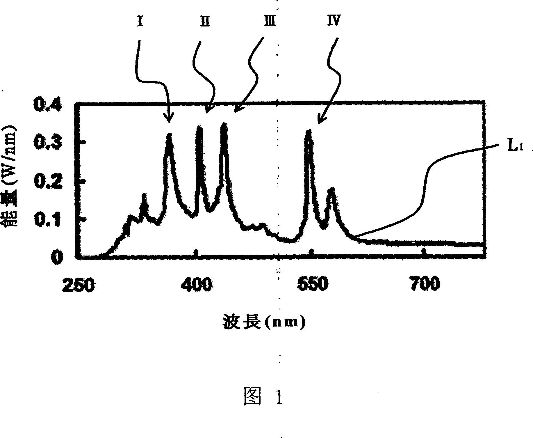
[0070] The present invention is directed to a projection display whose luminous frequency of a bulb includes an ultraviolet light component and a p...
PUM
 Abstract
Description
Claims
Application Information