
Air supplemental heat transfer engine

A technology of engine and gas storage, which is applied in open gas positive displacement engine factories and other directions, and can solve problems such as discontinuous movement of pistons

Inactive Publication Date: 2007-08-08
赛星嘎
View PDF3 Cites 4 Cited by
  • Summary
  • Abstract
  • Description
  • Claims
  • Application Information

AI Technical Summary

Problems solved by technology

In addition, the ideal motion of the engine piston is a continuous motion, so the external heating closed engine of the present invention can solve the technical problem that the ideal motion of the piston in the existing heat engine is a discontinuous motion.

Method used

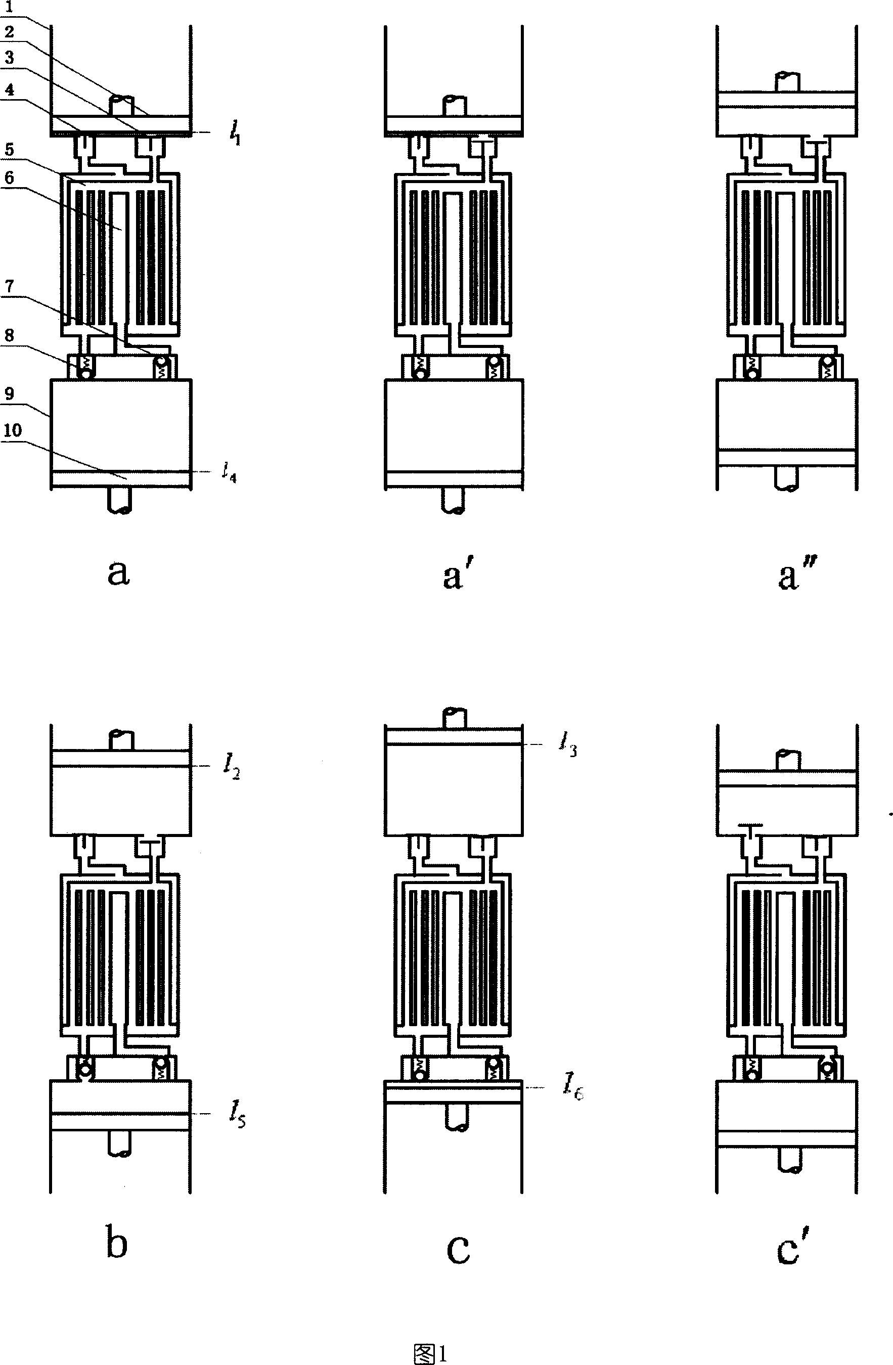
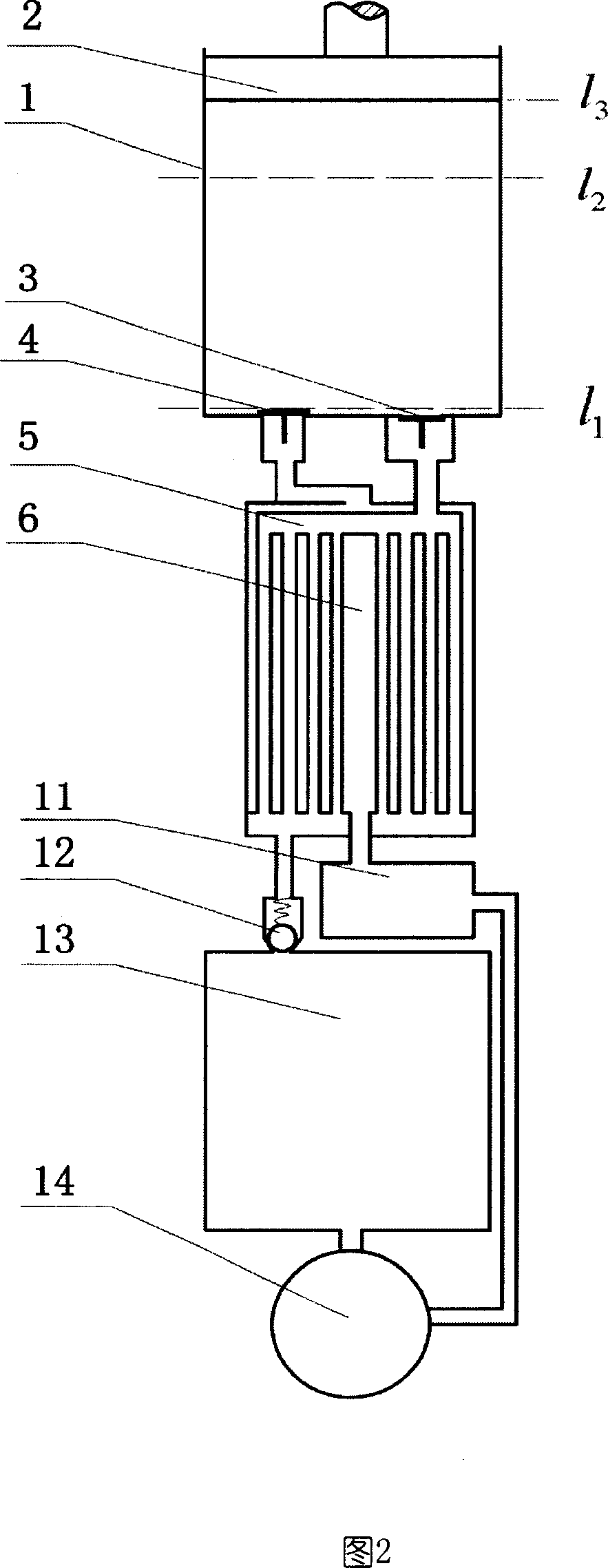
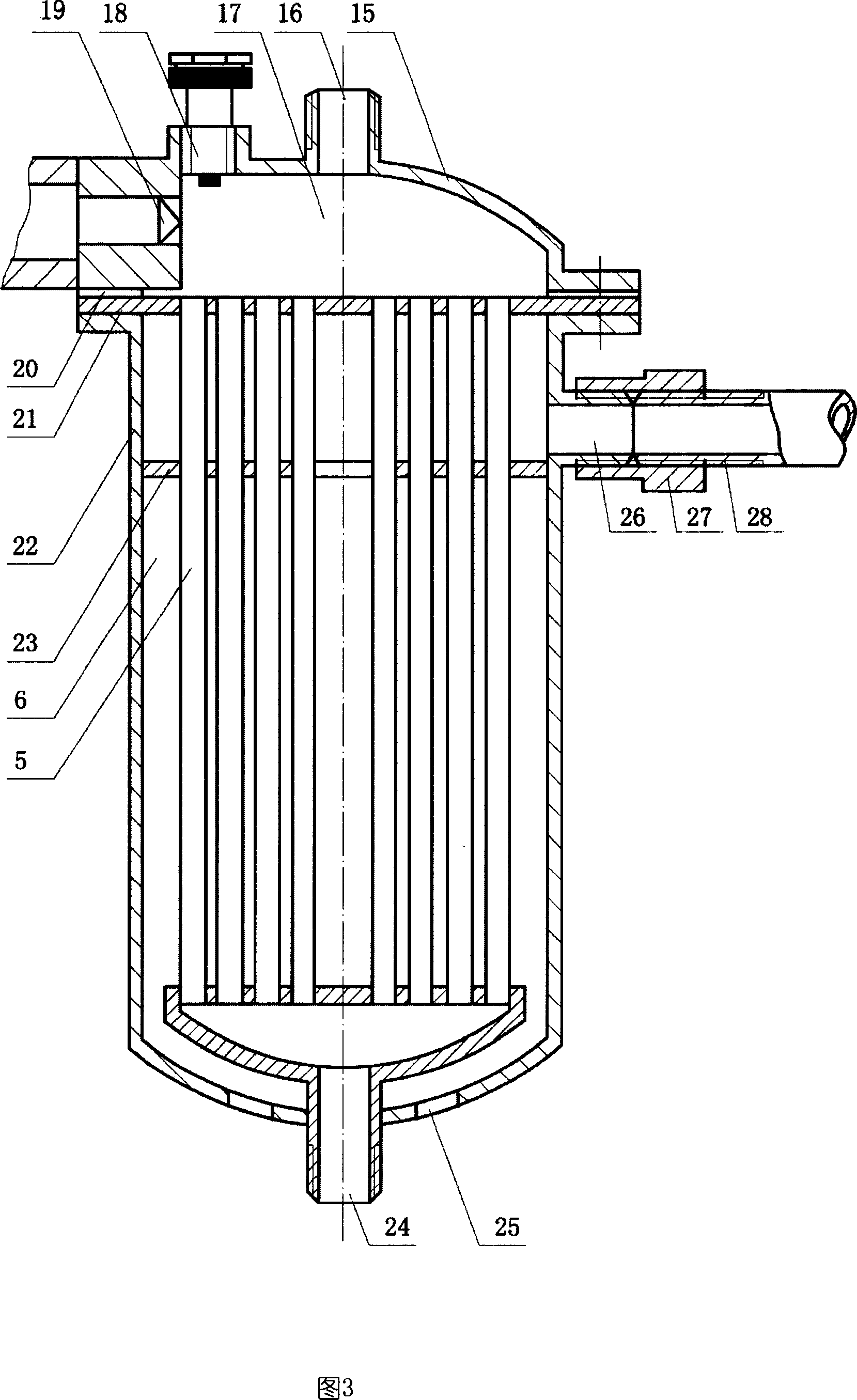

Image

  • Air supplemental heat transfer engine
  • Air supplemental heat transfer engine
  • Air supplemental heat transfer engine

Examples


Embodiment approach

[0060] The microcomputer-controlled air distribution mechanism arranged on the hot cylinder head is shown in Figure 6, and the structure of the intake valve is shown in Figure 7. When the hot cylinder 1 requires intake air, the microcomputer 59 controls the coil 57 to open the intake valve 3 (sheet The right end of shape gas valve 3 leaves valve port), and gas enters in the thermal cylinder by inlet 34 and valve port. Electric current stops in coil 57 under the control of microcomputer 59 when needing to close intake valve, and now the rebound of spring 67 pushes down the right end of sheet intake valve rapidly through electromagnet 68 and pull bar 56, and blocks valve port.

[0061] The structure of the exhaust valve is as shown in Figure 8. When the hot cylinder needs to be exhausted, the microcomputer 59 controls the coil 53 to open the exhaust valve 4. When the exhaust valve needs to be closed, the electric current of the coil 53 under the control of the microcomputer 59 st...


PUM


Abstract

The invention discloses an air storing and heat exchanging engine, mainly comprising hot air cylinder, heater, air storing room I, compressor and air storing room II. The compressor is connected with the cooling system. When the engine works, the high-temperature heat source transfers heat to the air in inner cavity of heater pipes and on the cover of heat cylinder there is a microcomputer control valve mechanism. The theoretical cycle of engine comprises two equal temperature processes, two equal cubage processes and a moving process. In the moving process energies can not be exchanged in system and the work that the outside puts to system is zero. So the cycling efficiency is equal to carnot cycle efficiency. Compared with the linkage-crank internal combustion engine the open engine, which works in the cycle, can save energy by more than 10%. Compared with prior stirling engine the transmission structure of closed engine is simple.

Description

Technical field [0001] The invention relates to an engine, especially an air storage type heat exchange cycle engine whose theoretical thermal efficiency is equal to the efficiency of the Carnot cycle. Background technique [0002] Internal combustion engines are widely used in various machinery or transportation machinery that needs to move. The theoretical cycle efficiency of the existing internal combustion engines is lower than the Carnot cycle efficiency, and the current internal combustion engines mainly use a connecting rod crank mechanism to convert the movement of the piston into rotation. This reciprocating mechanism has problems such as large sliding friction losses, so The efficiency is only 30% to 40%. In recent years, engines without connecting rod crank mechanisms have been studied both at home and abroad, such as microcomputer-controlled rack engines, 0410022121.2, rolling screw engines, ZL01214405.3, ZL02221857.2, all of which have problems such as lower th...

Claims


Application Information

Patent Timeline
IPC IPC(8): F02G1/02
Inventor 赛星嘎
Owner 赛星嘎
Learn More