Method for diagnosing a fuel supply system of an internal combustion engine

A fuel supply system and fuel supply technology, applied in the charging system, internal combustion piston engine, combustion engine, etc., to achieve the effect of realizing heat dissipation, reducing the compression area, and avoiding the diagnosis process time

Inactive Publication Date: 2007-08-08
AUDI AG +1
View PDF3 Cites 19 Cited by
  • Summary
  • Abstract
  • Description
  • Claims
  • Application Information

AI Technical Summary

Problems solved by technology

The fuel pressure drop on the basis of LPG-fuel pressure in the overall

Method used


Image

  • Method for diagnosing a fuel supply system of an internal combustion engine
  • Method for diagnosing a fuel supply system of an internal combustion engine

Examples


Example Embodiment

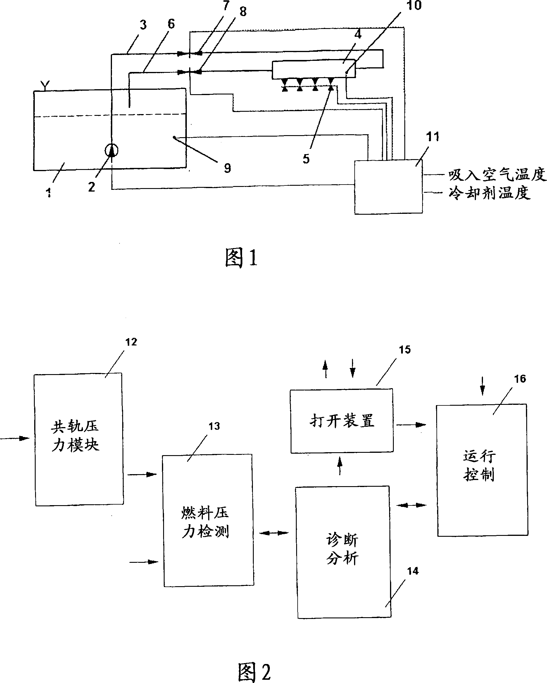
[0017] FIG. 1 shows a schematic diagram of a fuel supply system such as LPG fuel. Liquid LPG-fuel is stored in the fuel tank 1 . The liquid LPG fuel in the fuel supply line 3 is conveyed into the common rail 4 by means of the fuel pump 2 . At least one fuel nozzle 5 is arranged on the common rail 4 . The LPG fuel not pumped in at the fuel nozzle 5 is fed back into the fuel tank 1 in the fuel return line 6 . Shutoff valves 7 and 8 are provided in the fuel supply line 3 and the fuel return line 6 . A temperature measuring point 9 is arranged in the fuel tank 1 and a pressure measuring point 10 is arranged in the common rail 4 . The fuel nozzle 5 , the fuel pump 2 , the shut-off valves 7 and 8 as well as the temperature measuring point 9 and the pressure measuring point 10 are connected to a controller 11 in addition to elements for detecting the temperature of the intake and cooling water. The controller 11 corresponds to today's state of the art, that is to say it is also u...


PUM


Abstract

The invention relates to a method for diagnosing the fuel supply system of an internal combustion engine which operates, preferably, by gas and/or bivalently. Diagnosis devices which detect leakages due to pressure tests in the tank or in the entire system are already known. The aim of the invention is to enable the fuel supply system to be diagnosed in a highly economical manner, within a short space of time and whilst the internal combustion engine is operated. Temperature fluctuations and pressure conditions during the operation of the internal combustion engine should also be taken into account. According to the invention, the fuel pressure test takes place in individually closed volumes of the fuel supply system, wherein, preferably, defined partial areas of the supply system are separated by means of individually separates valves (7, 8) and are diagnosed by means of pressure tests.

Description

technical field [0001] The invention relates to a method for diagnosing a fuel supply system of an internal combustion engine according to the preamble of claim 1 . Background technique [0002] It is known that, in addition to CNG (compressed natural gas), LPG (liquefied petroleum gas) is also used in the automotive sector as a possible alternative fuel. Drives based on LNG (liquefied natural gas) and H2 (hydrogen) as alternative fuels are currently being discussed within the scope of this concept. In particular, so-called dual-drive concepts are currently being developed more and more, in which a known internal combustion engine can be driven not only with a first liquid fuel, but also with a second liquid or gaseous fuel. [0003] Document DE 10 255 345 A1 describes an LPG fuel supply system for motor vehicles with a fuel pump arranged in an LPG fuel tank. The LPG fuel is brought to an overpressure state by means of the fuel pump, so that the LPG fuel is present in a li...

Claims


Application Information

Patent Timeline
IPC IPC(8): F02M65/00F02M63/02
CPCF02D19/025F02M21/0245F02M21/0242F02D19/027Y02T10/32F02M21/0221F02M25/0809Y02T10/30
Inventor H·克莱因B·贝克尔
Owner AUDI AG
Why Eureka
Try Eureka