Multifunctional micro friction wear testing machine

A wear test and micro-friction technology, which is applied in the field of testing machines, can solve the problems of inability to test torsion motion forms, large equipment volume, and large driving force, and achieve the effects of small error, reasonable layout, and large driving force

Inactive Publication Date: 2007-08-15
CHINA UNIV OF MINING & TECH
View PDF0 Cites 55 Cited by
  • Summary
  • Abstract
  • Description
  • Claims
  • Application Information

AI Technical Summary

Problems solved by technology

The electro-hydraulic servo drive method is adopted, which has the advantages of large driving force, wide range of amplitude and frequency fluctuations, and easy use of computer program control and measurement, but the technology is more complicated, the cost is higher, and the equipment volume is also larger.
[0003] For the above-mentioned wear forms, there are already many kinds of testing machines, such as M2000 friction and wear testing machine, vertical universal wear t

Method used


Image

  • Multifunctional micro friction wear testing machine
  • Multifunctional micro friction wear testing machine
  • Multifunctional micro friction wear testing machine

Examples


Embodiment 1

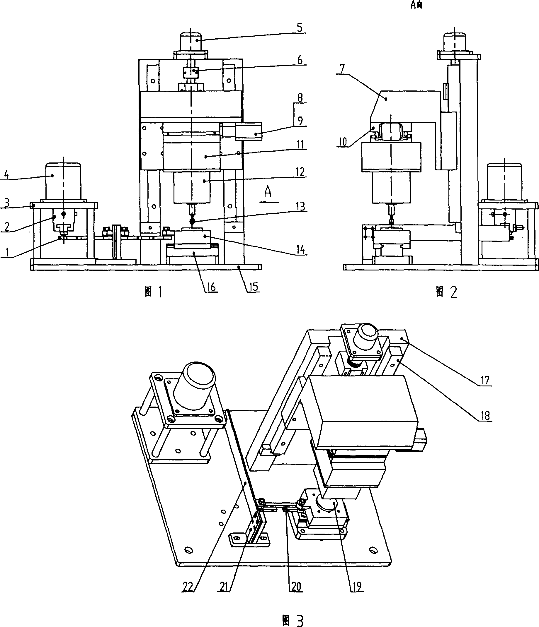
[0022] Embodiment 1: As shown in Fig. 1, Fig. 2 and Fig. 3, the micro-friction and wear testing machine is composed of a driving device, a moving device, a loading and measuring device and a lifting platform arranged on the bottom plate 15, and the driving device passes through a cantilever fixed on the support 21 The elastic plate 22 and the connecting rod 1, 20 are hinged together with the movement device. According to the proportional amplification and elastic bending effect of the cantilever elastic plate 22, a small vibration amplitude is generated at the hinge joint between the cantilever elastic plate 22 and the connecting rod 20, and the small amplitude is generated by the connecting rod. Transfer to the sliding table (or rotating table). The loading and measuring device is connected with the lifting platform and is located above the moving device. The driving device is composed of a motor bracket 3, a stepping motor 4 and an eccentric body 2, the stepping motor 4 is a...

Embodiment 2

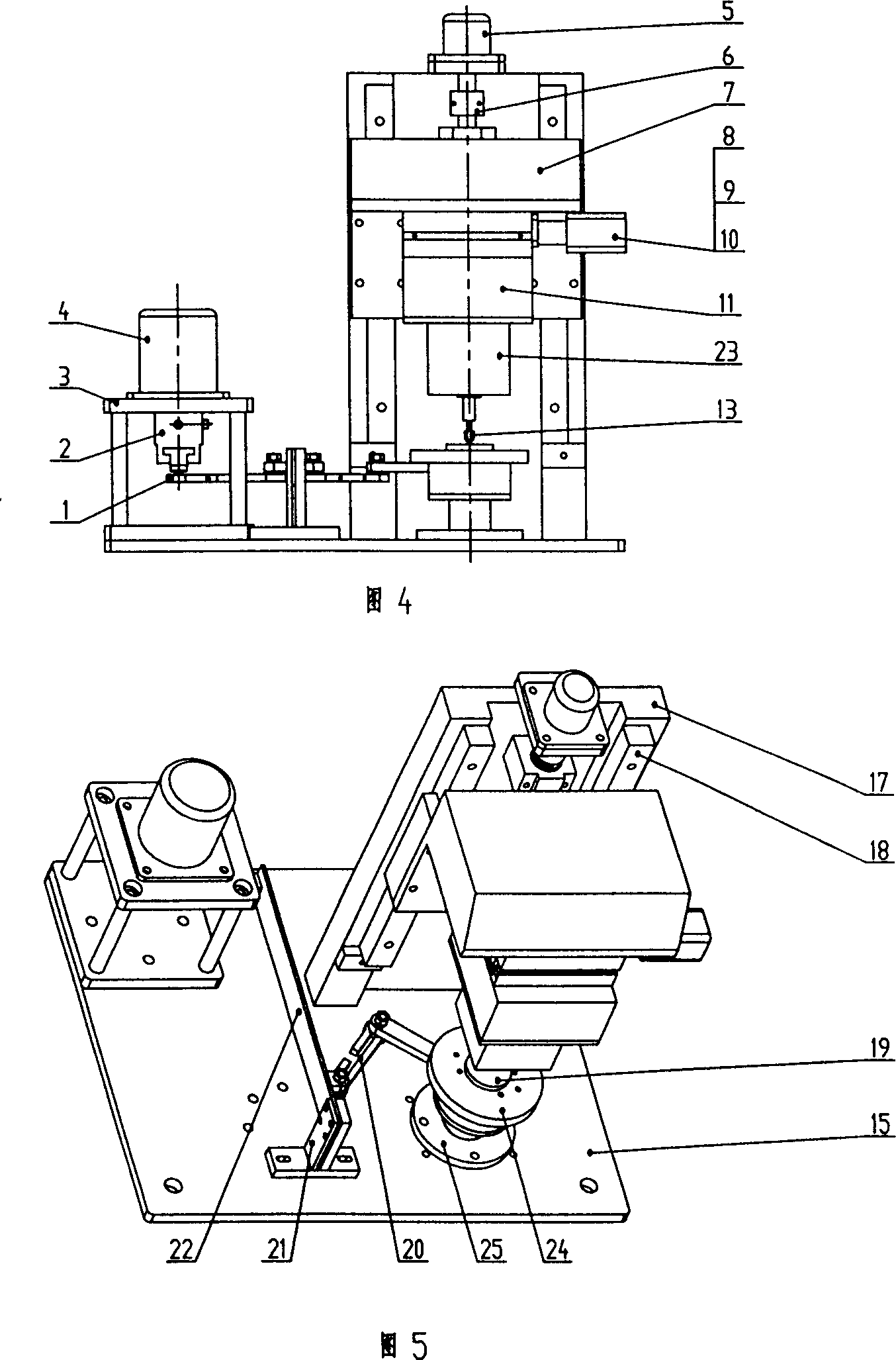
[0023] Embodiment 2: As shown in Fig. 4 and Fig. 5, the components of the mechanism are basically the same as in Embodiment 1, the difference is that the movement device connected to the drive device is composed of a support 25 and a rotating table 24 matched therewith, and the lower sample 19 It is fixed on the turntable 24, and the sensor in the loading and measuring device corresponding to the turntable 24 is a torque sensor 23. The turntable 24 is hinged with the connecting rod 20, and twists back and forth together with the connecting rod 20, so that the lower sample 19 and the upper sample 13 generate twisting friction and wear motion, and the magnitude of the torque is detected by the torque sensor 23.

Embodiment 3

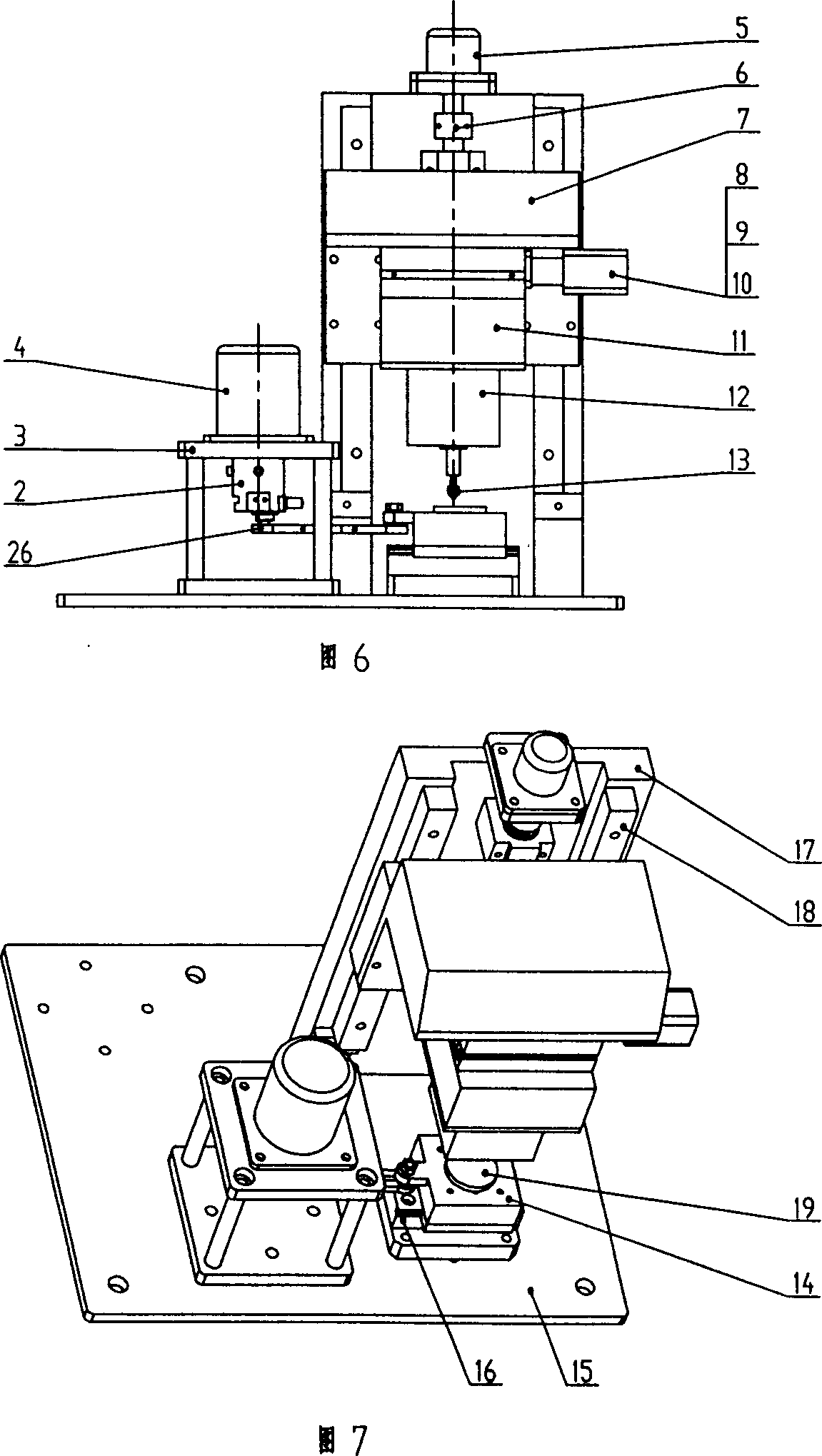
[0024] Embodiment 3: As shown in Fig. 6 and Fig. 7, the mechanism components are basically the same as in Embodiment 1, the difference is that the connecting rod 26 of the driving device is directly hingedly connected with the sliding table 14 of the moving device, and the driving device is located close to the On the side of the moving device, the bracket 21 and the cantilever elastic plate 22 arranged on the bracket 21 are removed. Since the proportional amplification link of the cantilever elastic plate is reduced in the middle, the slide table 14 can obtain a relatively large linear reciprocating motion, so that the lower sample 19 and the upper sample 13 produce friction and wear motion with relatively large amplitude, and the magnitude of the friction force is detected by the force sensor 12 .


PUM


Abstract

This invention relates to one multi-function micro friction test machine, which comprises drive device, move device connected to the drive one and load and measurement device on the move device and lift bench of the measurement device, wherein, it uses hanging spring board and connection bar are hinged with drive device and move device to make the slide bench generate one small range reverse line move under bar push with constant vibration range and small error; it uses motor to drive connection bar push slide to generate large vibration reverse line move.

Description

technical field [0001] The invention relates to a testing machine, in particular to a multifunctional micro-friction and wear testing machine. Background technique [0002] When two objects in contact with each other undergo relative motion or tend to move relative to each other under the action of external force P, the tangential resistance F generated on the contact surface is called friction force, and this resistance phenomenon is called friction. According to the motion form of the kinematic pair, it can be divided into sliding friction and rolling friction. In the laboratory, the forms of sliding friction mainly include ring-one-piece type, pin-disk type, end-face friction type, and fretting wear type. The fretting wear testing machine produces small-amplitude relative sliding between two contact surfaces, and the small-amplitude sliding mainly includes three methods: mechanical drive, fluid drive and electromagnetic drive. The mechanical drive can utilize cams, lever...

Claims


Application Information

Patent Timeline
IPC IPC(8): G01N19/00G01N3/56
Inventor 张德坤葛世荣吴虎城李伟王庆良
Owner CHINA UNIV OF MINING & TECH
Why Eureka
Try Eureka