Measurement and display method for film thickness reflectivity of optical coated film

A technology of optical coating and display method, which is applied in the measurement of scattering characteristics, optics, optical components, etc., can solve the analysis, evaluation, improvement and adjustment, cannot visually see the change of the real-time value of the reflectance of the coating, and cannot perform coating. Monitor system performance and other issues

Active Publication Date: 2007-08-15
HENAN COSTAR GRP CO LTD +1
View PDF0 Cites 14 Cited by
  • Summary
  • Abstract
  • Description
  • Claims
  • Application Information

AI Technical Summary

Problems solved by technology

This method cannot visually see the change of the real-time value of the reflectivity of the coating and the reflectivity value of the stop evaporation point
Moreover, due to the influence of various random factors such as temperature, vacuum degree and evaporation rate in the coating machine, the voltage signal cannot accurately reflect the real-time value of the reflectivity of the coating film itself, and it is also impossible to analyze the performance of the coating monitoring system. Evaluation and Adjustment for Improvement
For this problem, there is no better technical solution at home and abroad.

Method used


Image

  • Measurement and display method for film thickness reflectivity of optical coated film
  • Measurement and display method for film thickness reflectivity of optical coated film
  • Measurement and display method for film thickness reflectivity of optical coated film

Examples


Embodiment Construction

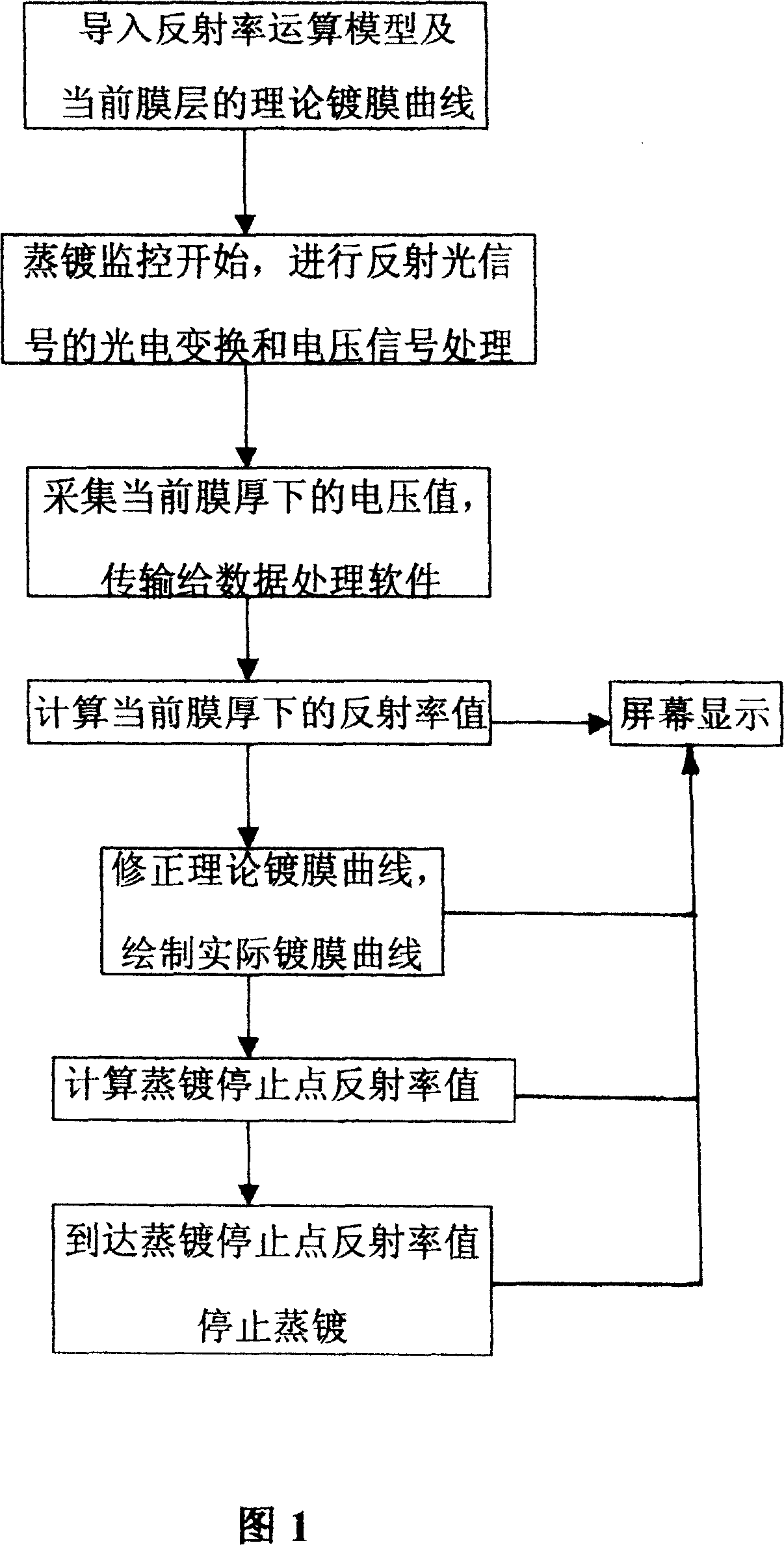
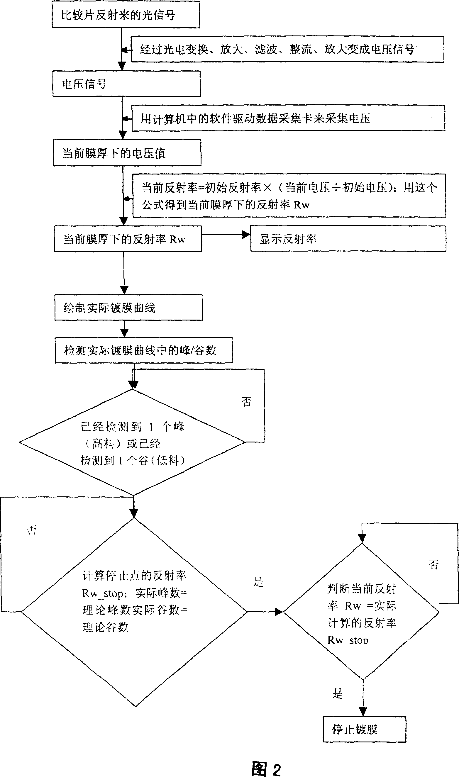
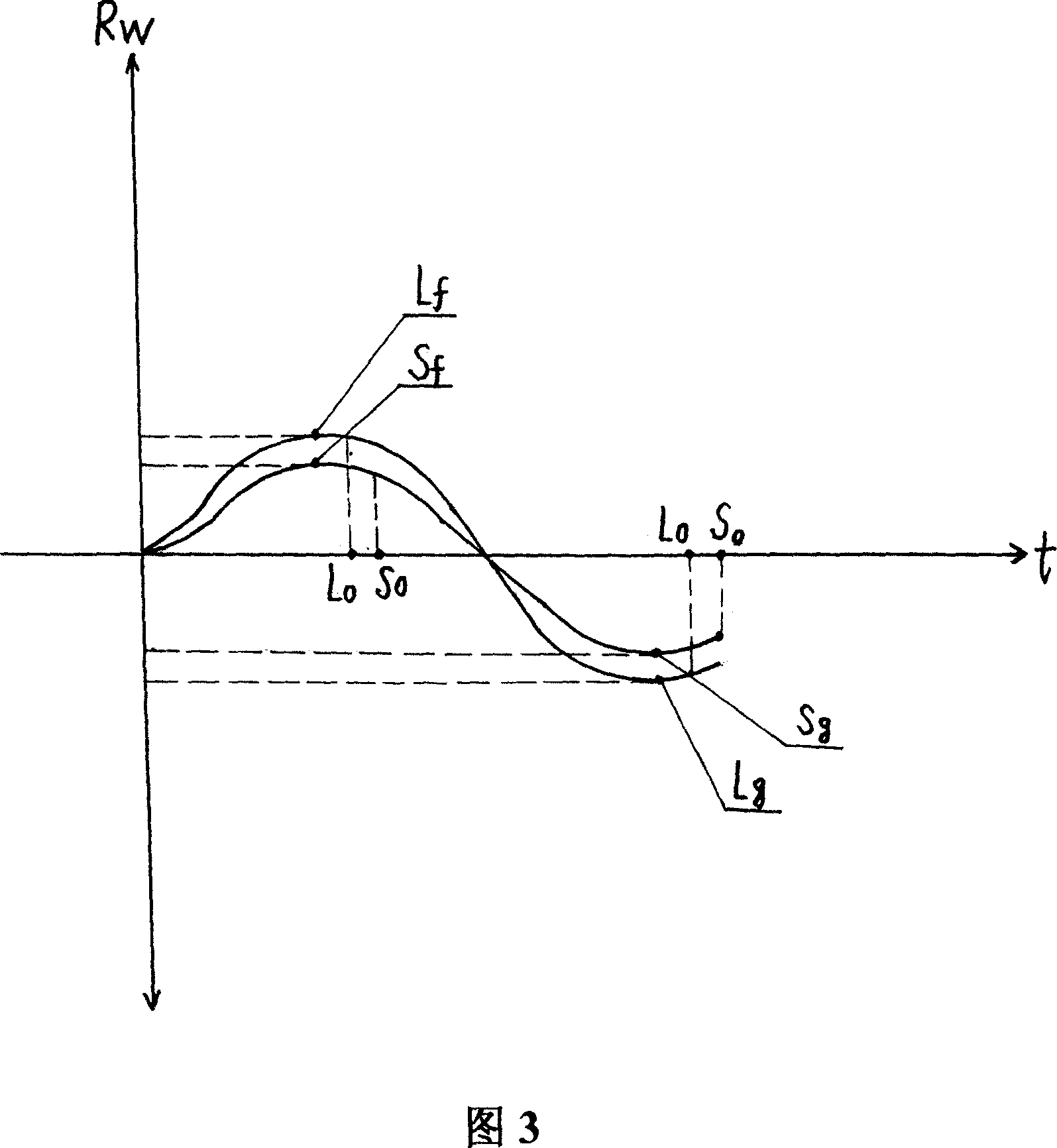
[0016] Referring to Figure 1 and Figure 2, in the process of optical coating, as the thickness of the film layer changes continuously, the reflectivity, refractive index and the corresponding reflected light energy are all changing, and the reflectivity or transmittance, the refractive index is the optical Main spectral characteristics of coated parts. Therefore, the monitoring of the thickness of the optical film is to measure and control the reflectivity or transmittance of the film. When monitoring, once the measured value reaches the value corresponding to the required film thickness, the evaporation baffle is immediately closed and the film layer is stopped. Evaporation. Therefore, the present invention utilizes the fast and accurate data processing function of the computer to conduct online measurement and real-time display of the change of reflectivity during the thin film evaporation process, so as to achieve the purpose of precisely controlling the thickness of the ev...


PUM


Abstract

This invention relates to one optical coat film reflection rate measurement and display method for optical film monitor, which uses computer for rapid data process function and processes online measurement and real time display in the coating process and determines the coat terminate point according to the coat film curve peak or trough point reflection value.

Description

technical field [0001] The invention belongs to the technical field of optical coating monitoring, in particular to a method for measuring and displaying the film thickness reflectance of an optical coating. Background technique [0002] At present, in optical coating, an optical monitoring system is generally used to monitor and control the coating film thickness, that is, the light beam emitted by the light source system is modulated, collimated, and split, and then projected onto the comparison sheet, and then the film thickness optical signal reflected by the comparison sheet Projected on the photoreceptor, after photoelectric conversion, a voltage signal with film thickness information is obtained. When the voltage signal reaches a certain extreme value set by theoretical calculation or experimental conditions, it is considered that the coating has reached the required thickness and the evaporation is stopped. This method cannot visually see the change of the real-time...

Claims


Application Information

Patent Timeline
Patent Type & Authority Applications(China)
IPC IPC(8): G02B1/10G01M11/02G01N21/55
Inventor 赵升林孙龙菊池和夫
Owner HENAN COSTAR GRP CO LTD
Why Eureka
Try Eureka