Base plate structure and method for producing thin film pattern layer

A thin film pattern and manufacturing method technology, which is applied in the field of thin film pattern layer manufacturing, can solve the problems of thin film pattern layer yield drop, etc., and achieve the effect of high product yield and improved product yield

Inactive Publication Date: 2007-08-22
ICF TECH
View PDF0 Cites 5 Cited by
  • Summary
  • Abstract
  • Description
  • Claims
  • Application Information

AI Technical Summary

Problems solved by technology

However, the inkjet method uses a general retaining wall structure. When the ink 314 is excessively filled and overflows to the surroundings, the overflow ink 314 will mix with the ink in the adjacent storage space to make the film pattern layer formed after drying and curing. decline

Method used


Image

  • Base plate structure and method for producing thin film pattern layer
  • Base plate structure and method for producing thin film pattern layer
  • Base plate structure and method for producing thin film pattern layer

Examples


Embodiment Construction

[0018] The embodiments of the present invention will be further described in detail below in conjunction with the accompanying drawings.

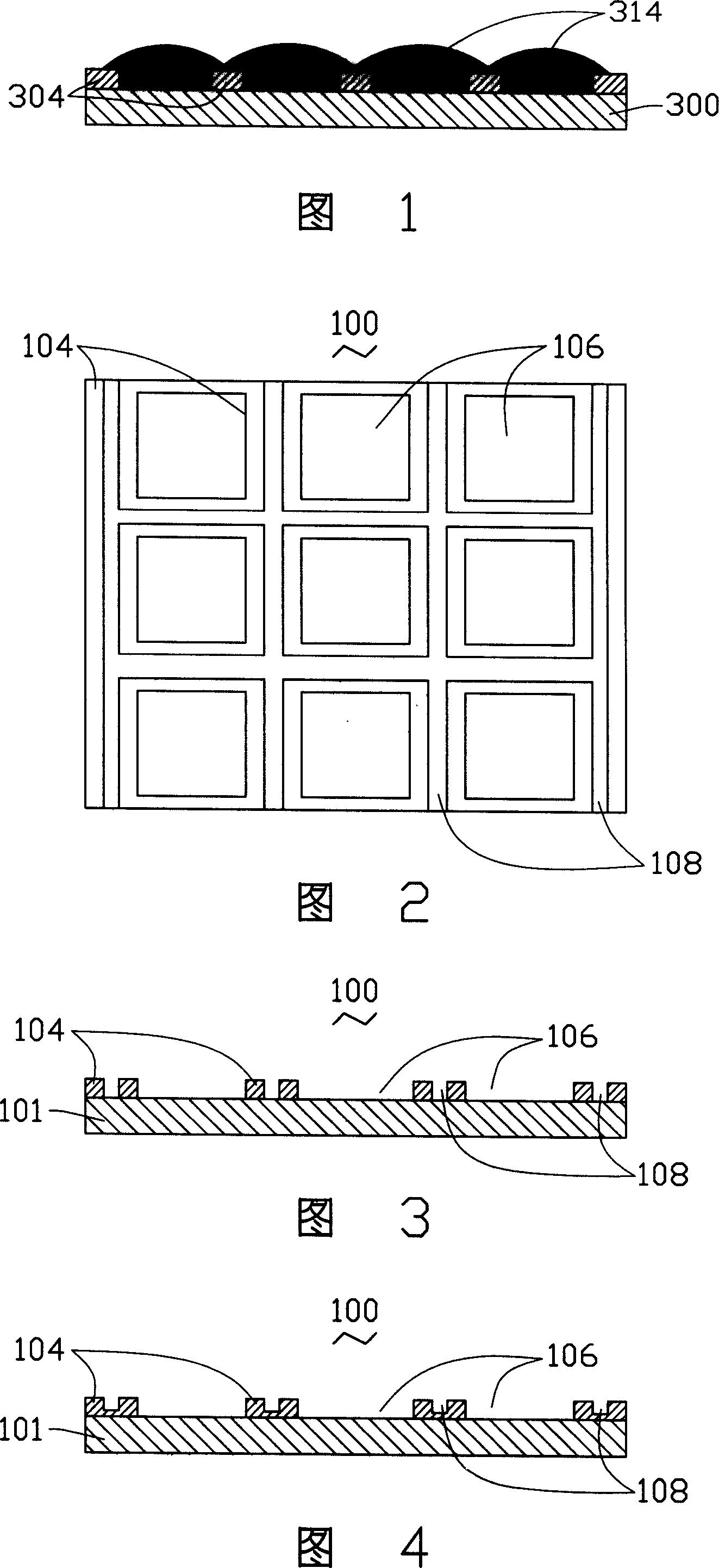
[0019] Please refer to FIG. 2 to FIG. 3 together. The first embodiment of the present invention provides a substrate structure 100 , which includes: a substrate 101 and a plurality of retaining walls 104 located on the substrate 101 .

[0020] In this embodiment, the substrate 101 is selected from glass. Certainly, the substrate 101 may also be selected from quartz glass, silicon wafer, metal plate or plastic plate, and the like. Wherein, the plurality of barrier walls 104 are formed on the substrate 101 by photolithography (details will be described later), or the substrate 101 and the plurality of barrier walls 104 are integrally formed (details will be described later).

[0021] A plurality of first receiving spaces 106 are formed between the plurality of retaining walls 104 and the substrate 101 , and the first receiving spaces 106 are...


PUM


Abstract

The invention relates to a substrate structure, comprising a substrate and multiple barriers formed on the substrate, where multiple first holding spaces are formed between these barriers and the substrate to hold the ink injected by an ink jet device, and the barrier between two adjacent first holding spaces comprises at least a second holding space to hold the overflowing ink from the first holding spaces, thus able to avoid the ink in the two adjacent first holding spaces from mixing with each other. And the invention also relates to a film pattern layer making method, comprising the steps of: providing an above substrate structure; filling ink into the first holding spaces by an ink jet device; and drying and curing the ink in the first holding spaces to form the film pattern layer.

Description

【Technical field】 [0001] The invention relates to a substrate structure and a method for manufacturing a thin film pattern layer. 【Background technique】 [0002] At present, the methods for manufacturing the thin film pattern layer mainly include photolithography and inkjet methods. [0003] Photolithography method: by coating a photoresist material on the substrate structure prepared to coat the required film, setting a photomask with a predetermined pattern on the photoresist material, exposing and developing, or adding an etching process, and A thin film pattern layer having a preset pattern is formed. The photolithography method requires large-scale equipment such as vacuum devices or complex manufacturing processes, and the use efficiency of materials is low, resulting in high manufacturing costs. [0004] Inkjet method: as shown in Figure 1, an inkjet device is used to spray ink 314 formed by the required thin film material into the accommodation space formed by a pl...

Claims


Application Information

Patent Timeline
Patent Type & Authority Applications(China)
IPC IPC(8): G03F7/20G03F7/32G02F1/133G02B5/23B41J2/01
Inventor 周景瑜
Owner ICF TECH
Why Eureka
Try Eureka