Multi travelling wave bending-rotation ultrasonic motor stator and ultrasonic motor using same

An ultrasonic motor and stator technology, applied in the direction of generator/motor, piezoelectric effect/electrostrictive or magnetostrictive motor, electrical components, etc., can solve the problem of small torque, low output speed, and unsatisfactory working stability of the motor and other problems, to achieve the effect of increasing stability, increasing output torque, and simple processing technology

Inactive Publication Date: 2007-08-29
HARBIN INST OF TECH
View PDF3 Cites 26 Cited by
  • Summary
  • Abstract
  • Description
  • Claims
  • Application Information

AI Technical Summary

Problems solved by technology

[0003] In order to solve the problems of unsatisfactory motor working stability, low output speed, small torque and low energy conversion efficiency of the whole machine caused by the single-point contact of the stator and rotor of the existing bending and rotating ultrasonic motor, the present invention designs a multi-traveling wave bending and rotating Ultrasonic motor stator and ultrasonic motor using the stator

Method used


Image

  • Multi travelling wave bending-rotation ultrasonic motor stator and ultrasonic motor using same
  • Multi travelling wave bending-rotation ultrasonic motor stator and ultrasonic motor using same

Examples


specific Embodiment approach 1

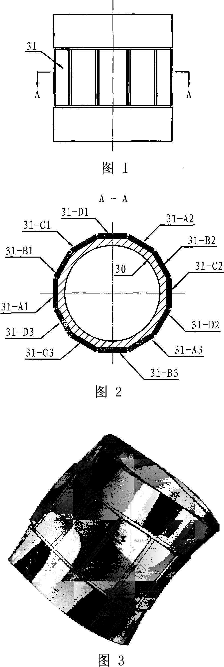
[0008] Specific Embodiment 1: Refer to FIG. 1 to FIG. 5 to illustrate this embodiment. The stator of the multi-travel wave bending and rotating ultrasonic motor in this embodiment is composed of a stator base and electrodes. The number of electrodes is 4n, where n is a natural number greater than or equal to 2, and the 4n electrodes are evenly distributed along the circumference of the stator base. It is fixed on the outer surface of the wave crest when the stator base generates first-order bending vibration. The 4 adjacent electrodes in the 4n electrodes form a group and are divided into n groups. The 4 adjacent electrodes in each group are respectively Lines that apply sine waves (sin(ωt)), cosine waves (cos(ωt)), negative sine waves (-sin(ωt)), and negative cosine waves (-cos(ωt)) at the same or close to the natural frequency of the stator Wave excitation signal.

[0009] The stator base in this embodiment is a metal tube 30, and the electrodes are piezoelectric ceramic sh...

specific Embodiment approach 2

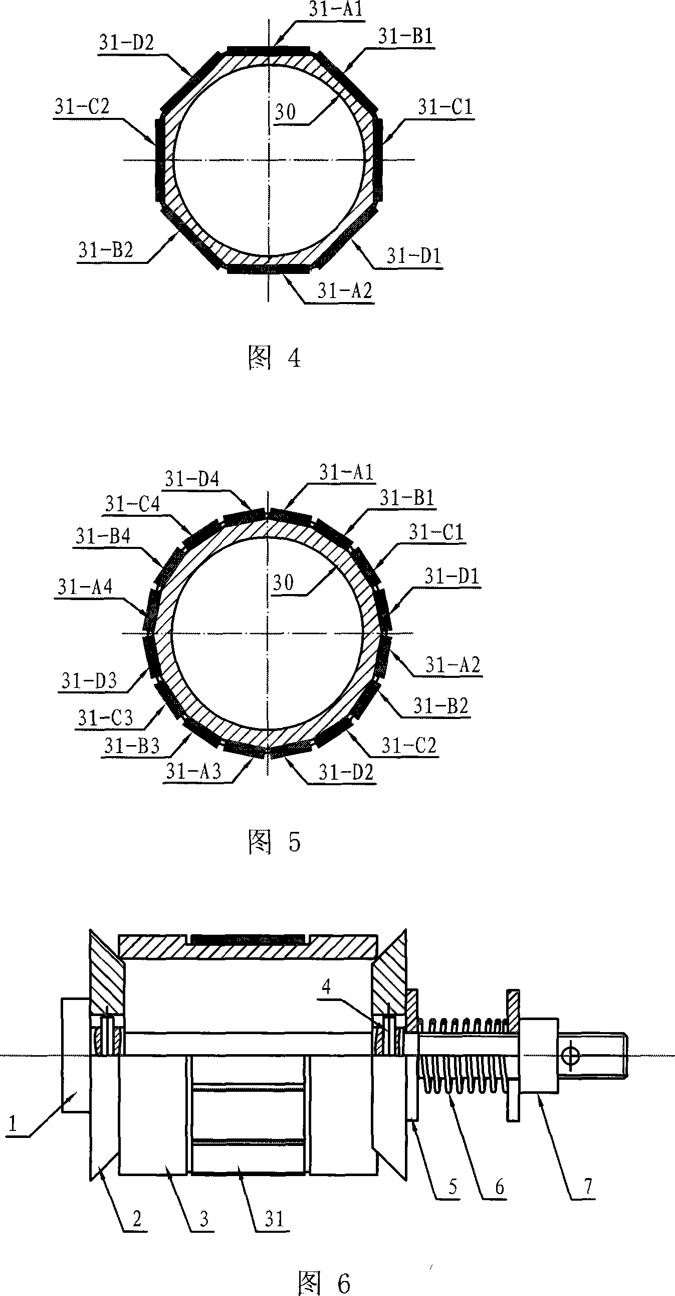
[0014] Specific Embodiment 2: Refer to FIG. 6 to illustrate this embodiment. The ultrasonic motor of the present embodiment is made up of two rotors 2, a stator 3 and a pre-pressure mechanism. Contact, the rotor 2 is connected with the rotor shaft 1 through the positioning key 4; the washer 5, the pressurizing spring 6 and the adjustment nut 7 of the pre-pressure mechanism are sequentially sleeved on the torque output end of the rotor shaft 1, and the stator 3 is a specific embodiment. The multi-traveling wave bends and rotates the stator of an ultrasonic motor.

[0015] In this embodiment, the tapered surface of the rotor 2 in contact with the stator 3 is coated with polymer friction material or ceramic coating friction material. The polymer friction material can be selected from polytetrafluoroethylene, polyphenylene sulfide, polyether ether ketone or polyphenylene ester and composite materials thereof, and the ceramic coating friction material can be selected from DLC film...


PUM


Abstract

The invention solves issues: poor working stability, low output rotation speed, small moment, and low efficiency of energy conversion caused by singlepoint contact between stator and rotor, existed in current ultrasonic electrical motor (UEM). The stator of bending revolving UEM in multiple traveling waves is composed of base body of stator, and 4n pieces of poles, and where n is natural number larger than or equal to 2. Being distributed on circle of base body of stator evenly, 4n pieces of poles are fixed on external surface of wave crest when base body of stator generates first order bending vibration. 4 pieces of poles are grouped, and there are total n groups. Actuating signals of traveling wave including sine wave, cosine wave, minus sine wave, and minus cosine wave near to or identical to natural frequency of stator are applied to 4 poles in a group. The disclosed UEM includes n contacts between stator and rotor so as to solve the said issues.

Description

technical field [0001] The invention relates to the field of ultrasonic motors. Background technique [0002] Ultrasonic motor is a new type of direct drive motor that uses the inverse piezoelectric effect of piezoelectric ceramics to excite ultrasonic vibrations, and through friction drive, realizes the conversion of electrical energy into mechanical energy output. Among them, the bending and rotating ultrasonic motor is a kind of traveling wave ultrasonic motor. It excites the piezoelectric ceramic element on the stator to make the stator generate two orthogonal vibrations bending along the axial direction. Traveling waves distributed along the circumference are formed, and the rotor is in contact with the stator under the action of preload, and the rotor is driven to rotate by friction. The stator of the bending and rotating ultrasonic motor in the prior art can be divided into four exciting regions for excitation, such as "Double Rotor Cylindrical Traveling Wave Type Si...

Claims


Application Information

Patent Timeline
Patent Type & Authority Applications(China)
IPC IPC(8): H02N2/00H02N2/10H02N2/12
Inventor 曲建俊程廷海周宁宁
Owner HARBIN INST OF TECH
Why Eureka
Try Eureka