Air-conditioning device

An air conditioning and air technology, applied in the field of air conditioning devices, can solve the problems of low efficiency of cooling operation

Inactive Publication Date: 2007-09-12
DENSO CORP
View PDF3 Cites 23 Cited by
  • Summary
  • Abstract
  • Description
  • Claims
  • Application Information

AI Technical Summary

Problems solved by technology

That is, the operating efficiency of the cooling operation of the air conditionin...

Method used


Image

  • Air-conditioning device
  • Air-conditioning device
  • Air-conditioning device

Examples


Embodiment Construction

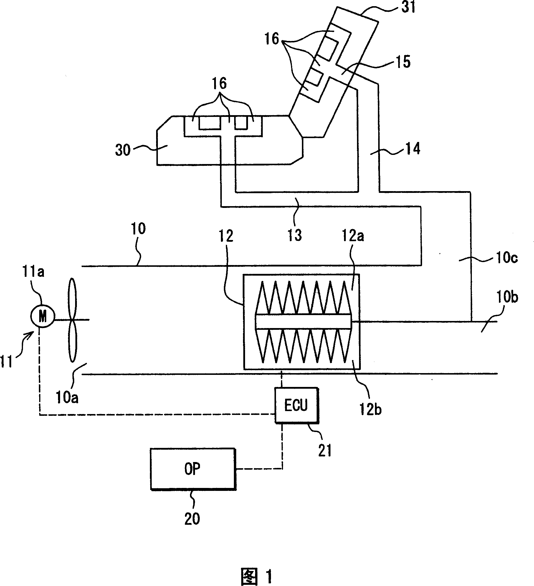
[0016] As shown in FIG. 1 , an air conditioning device is typically used for a vehicle seat having a seat cushion 30 and a seat back 31 and includes a duct 10 . The duct 10 has a suction portion 10a for introducing air (ie, interior air) from a vehicle compartment. A fan 11 (pump) is provided at the suction portion 10a. The fan 11 includes a centrifugal bladed impeller driven by a direct current (DC) motor 11a. The air delivery amount (blow air amount) of the fan 11 can be controlled by the voltage applied to the DC motor 11a.

[0017] A Peltier element 12 (thermoelectric conversion unit) is provided on the downstream side of the fan 11 in the duct 10 . The Peltier element 12 is formed by alternately stacking p-type semiconductors and n-type semiconductors. The Peltier element 12 includes a first heat exchanger 12a and a second heat exchanger 12b. The duct 10 is divided into a first channel 10c and a second channel 10b (holes) on the downstream side of the Peltier element ...


PUM


Abstract

An air-conditioning device includes a pump for sending a thermal medium, a thermoelectric conversion unit for absorbing heat from the thermal medium, a target setting unit for setting a target cooling value, and a controlling unit. The controlling unit increases a flow amount of the thermal medium to be larger than a predetermined amount and stops the thermoelectric conversion unit from absorbing heat, when the target cooling value is smaller than a predetermined value. The controlling unit increases a heat-absorbing amount of the element and keeps the flow amount of the thermal medium to be larger than the predetermined amount, when the target cooling value is equal to or larger than the predetermined value.

Description

technical field [0001] The present invention relates to an air conditioning device using a thermoelectric conversion unit. Background technique [0002] JP-A-6-147524, JP-A-6-146371 or U.S. Patent No. 5,524,439 (corresponding to JP-A-9-505497) discloses an air conditioning device in which a Peltier element, ie, a thermoelectric conversion unit. [0003] Generally, a refrigeration cycle device performs a cooling operation by compressing and expanding a refrigerant in a refrigeration cycle, and has a coefficient of performance (COP) ranging between 3 and 4. However, air conditioners using Peltier elements have a COP in the range between 0.2 and 1. That is, the operating efficiency of the cooling operation of the air conditioning apparatus using the Peltier element is much lower than that of the refrigeration cycle apparatus. Contents of the invention [0004] In view of the foregoing and other problems, an object of the present invention is to provide an air conditioning ...

Claims


Application Information

Patent Timeline
IPC IPC(8): F24F5/00F25B21/02A47C7/74
CPCF25B2321/021B60H1/00478B60N2/5657B60N2/5692F25B21/02F25B2321/0251
Inventor 伊藤裕司青木新治泽井拓彦
Owner DENSO CORP
Why Eureka
Try Eureka