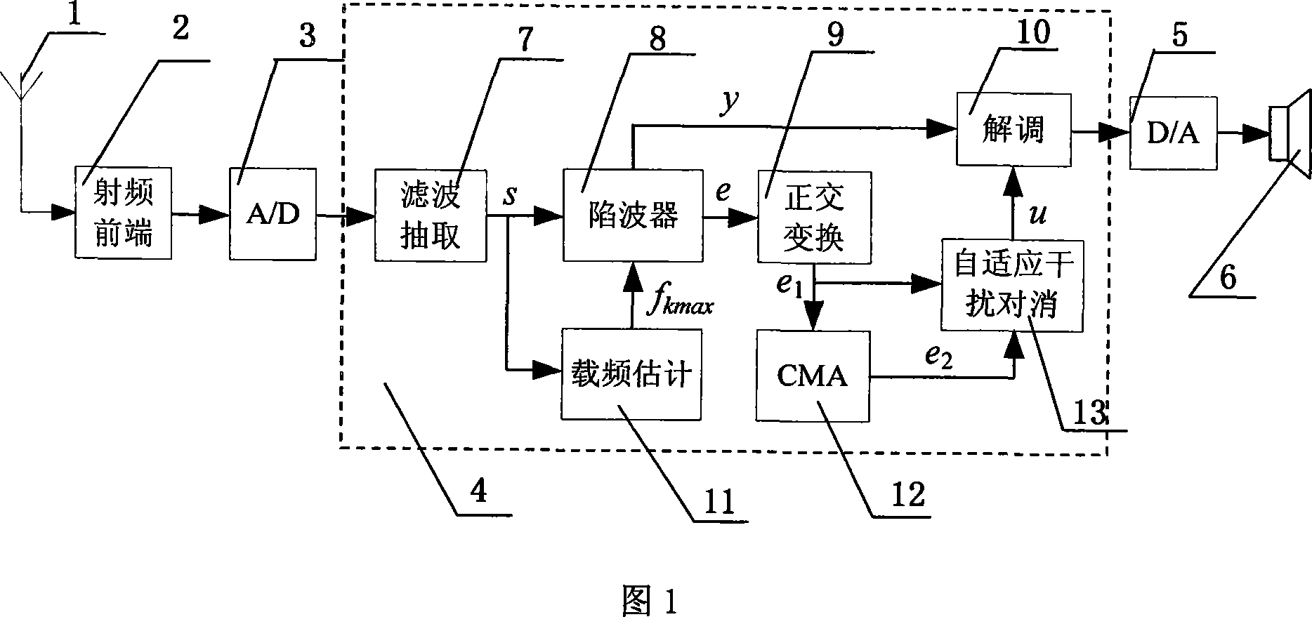
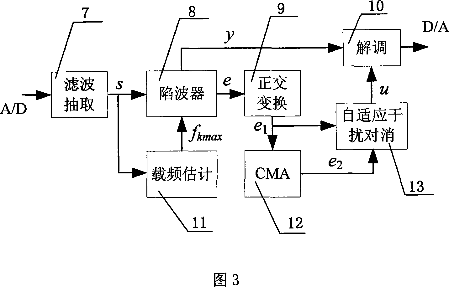
[0027] The single-channel-based civil aviation ground-air communication adaptive interference suppression method and system thereof of the present invention will be described in detail below with reference to the accompanying drawings and specific embodiments.
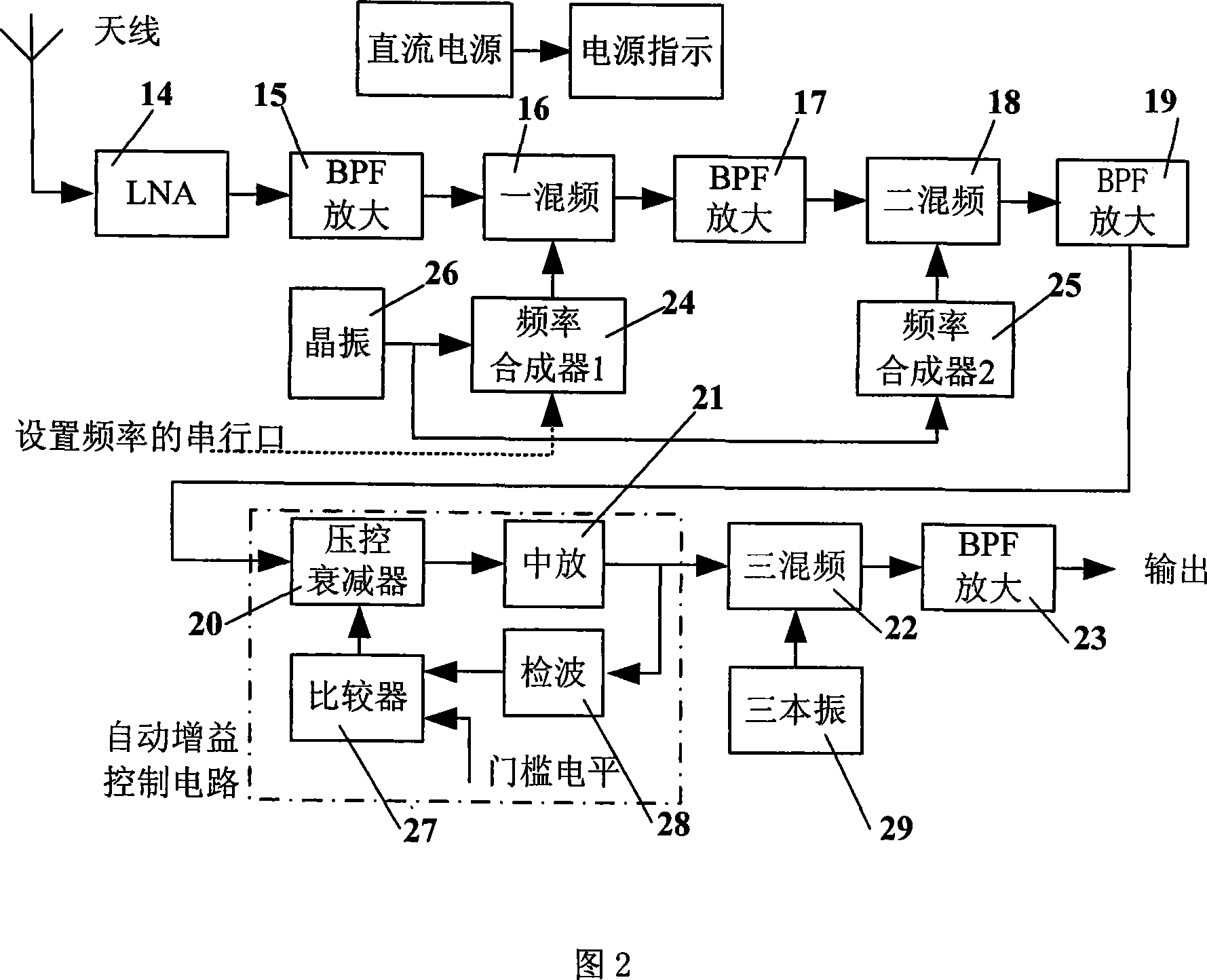
[0028] In order to further understand the present invention, below in conjunction with the technical characteristics of the civil aviation VHF (very high frequency) ground-to-air communication station, the specific implementation process of the present invention is given a detailed introduction.
[0029] The technical characteristics of VHF ground-to-air communication devices are specified in Volume I of Annex 10 of the International Convention. The radio adopts DSB-AM (double sideband amplitude modulation with carrier) and half-duplex communication. Its operating frequency range is 118.0MHz to 136.975MHz, and the channel spacing is 25KHz. It can provide 760 communication channels. These channels can be used in Reuse in a wide area.
[0030] For this reason, the civil aviation ground-air communication adaptive interference suppression method based on single channel of the present invention is to utilize the civil aviation ground-air communication self-adaptive interference suppression system based on single channel shown in Figure 1 to realize, the specific method is as follows:
[0031] In the first step, the VHF AM signal received by the antenna is converted into an intermediate frequency signal. First, let the interfered civil aviation ground-air communication AM signal pass through the RF front-end as shown in Figure 2. The RF front-end is composed of a low-noise high-frequency amplifier, a three-stage mixer and an automatic gain control circuit (the dotted box in Figure 2) , the radio signal is converted into a 1.25MHz intermediate frequency signal through the RF front end for subsequent signal processing.
[0032] In this embodiment, the circuits such as the low-noise high-frequency amplifier, the three-stage mixer and the automatic gain control circuit are realized by existing circuits or principles. The three-stage intermediate frequencies obtained after the three-stage frequency mixing are 465MHz, 70MHz, and 1.25MHz respectively.
[0033] Then the digitized intermediate frequency signal is passed through the adaptive interference suppression platform as shown in FIG. 3 , and the steps described later are performed. That is, the constant mode interference in the interfered AM signal is suppressed by using the adaptive interference suppression method of the present invention, and the signal-to-interference ratio is improved. Its adaptive interference suppression platform includes a filter extraction module, a carrier frequency estimation module, an adaptive notch filter, an orthogonal transformation module, a CMA (constant modulus algorithm) module, an adaptive interference canceller, and a demodulation module. Adaptive suppression of single constant mode interference in the process of civil aviation ground-air communication, improve the signal-to-interference ratio, and enhance the flight safety factor.
[0034] The second step is to digitally convert and filter the converted intermediate frequency signal. Implement data acquisition and analog-to-digital conversion on the analog intermediate frequency signal output by the RF front-end through the A/D conversion unit. In order to reduce the design requirements for subsequent digital filters, an over-sampling scheme is adopted in this embodiment, and the actually used sampling rate is 5 MHz, and the number of sampling bits is 12 bits. In the filter extraction module, the analog-to-digital conversion output digital signal is filtered and extracted, and the data rate is reduced from 5MSps to an appropriate level. The purpose is to improve the real-time performance and reduce the computation load of subsequent signal processing. In this embodiment, two stages of band-pass filter extraction are used, each extraction is 5 times, and finally the sampling rate is reduced to 200KSps.
[0035] The third step is to estimate the carrier frequency of the filtered and extracted signal on the basis of the known frequency range of the carrier frequency of the AM signal. Described carrier frequency estimation is to utilize the Goertzel algorithm to carry out carrier frequency estimation to the digital signal s (n) of filter extraction module output in the carrier frequency estimation module, and purpose is to provide a frequency initial value f for adaptive notch filter kmax , to improve the convergence speed of the notch filter.
[0036] The Goertzel algorithm used by the carrier frequency estimation module uses the rotation factor W N k = e - j 2 π / N periodicity W N - kN = 1 , The DFT (Discrete Fourier Transform) operation is expressed as a linear filter operation, and the form of the difference operation makes its recursion better. Figure 4 shows the recursive flowchart of the Goertzel algorithm, and its recursive expression is:
[0037] v k ( n ) = 2 cos 2 πk N v k ( n - 1 ) - v k ( n - 2 ) + s ( n ) - - - ( 1 )
[0038] f k ( n ) = v k ( n ) - W N k v k ( n - 1 ) - - - ( 2 )
[0039] In this embodiment, N in formula (1) and formula (2) is 200K, and k is the frequency point to be searched in the frequency range, and the initial condition of formula (1) is set to v k (-1) = v k (-2)=0, n=0, 1, . . . , N 1 , N 1 Take N/10 (that is, 20K), s(n) is the digital signal output by the filter extraction module, and output f k (n) is the frequency spectrum corresponding to frequency point k. In this embodiment, the specific flow of carrier frequency estimation based on the Goertzel algorithm is as follows:
[0040] (1) At each frequency point k, right, z=0, 1,..., N 1 Iterative calculation formula (1), then at n=N 1 Calculation formula (2), thus obtain the frequency spectrum of L frequency points (in the present embodiment, frequency point k is positioned at the frequency range of the center ± 500Hz with the estimated initial value of carrier frequency being 50KHz, and L is taken as 101, i.e. between the frequency points interval 10Hz);
[0041] (2) Calculate the spectrum f of L frequency points k (N 1 ) in the frequency point f corresponding to the maximum amplitude kmax (i.e. f for L points k (N 1 ) to take the modulus, find the maximum value of these moduli), and use this carrier frequency estimation value f kmax Update the frequency interval for the center as [f kmax -10Hz, f kmax +10Hz];
[0042] (3) Use new sampling data to restart the spectrum calculation of L frequency points for the updated frequency interval, and reach N again at the sampling point 1 Find the frequency point f corresponding to the maximum amplitude in the frequency spectrum of L frequency points kmax , with f obtained at this time kmax is the initial frequency value of the adaptive notch filter.
[0043] The fourth step is to use the estimated value of the carrier frequency as a reference signal to perform adaptive notching to trap the carrier in the AM signal, thereby avoiding the phenomenon of interference capture in the constant modulus algorithm. Described adaptive notch is carried out in the adaptive notch filter as shown in Figure 5, and its input signal has: the digital signal s (n) of filter extraction output and carrier frequency estimation output value f kmax , to output two signals: the output carrier signal y(n) is sent to the demodulation module for demodulation. The error output signal e(n) from which the carrier has been removed is connected to an orthogonal transformation module to convert it into a complex signal for subsequent adaptive signal processing.
[0044] The basic working process of the adaptive notch filter in Figure 5 is that the digital signal x(n) output by filtering and extraction passes through the IIR filter, and the error signal e(n) that removes the carrier is output:
[0045] e(n)=x(n)+a(n)x(n-1)+x(n-2)-ra(n)e(n-1)+r 2 e(n-2) (3)
[0046] where a(n) is the notch filter parameter that needs to be adjusted, it eventually converges to -2cosω 0 , divided by the trap at frequency ω 0 The AM carrier of , r is the polar radius of the notch filter, which should be slightly less than 1, and 0.99995 is taken in this embodiment.
[0047] For the update algorithm of a(n), shilling g ( n ) = ∂ e ( n ) ∂ a ( n ) , That is, the partial derivative of a(n) in formula (3) is obtained:
[0048] g(n)=x(n-1)-re(n-1)-ra(n)g(n-1)+r 2 g(n-2) (4)
[0049] Applying the LMS algorithm, the update formula of a(n) is obtained:
[0050] a(n+1)=a(n)-2μe(n)g(n) (5)
[0051] The corresponding trapped carrier y(n) is:
[0052] y(n)=x(n)-e(n) (6)
[0053] In formula (5), 0≤μ≤1 is the step size, and a(0) is the estimated value of the carrier.
[0054] Derived from the above, the steps of adopting the adaptive notch algorithm in this embodiment are as follows:
[0055] (1) Initialization: g(0)=g(-1)=0, e(0)=e(-1)=0, r=0.99995, μ=0.0001, a(0) is output by the carrier frequency estimation module The value is obtained, that is, -2cos(2πf kmax );
[0056] (2) calculate formula (3) and formula (4), obtain the error signal e (n) that removes carrier;
[0057] (3) Calculate formula (5) and formula (6), perform coefficient update and output carrier y(n), repeat step 2 and step 3.
[0058] In the fifth step, an orthogonal transformation is performed on the signal from which the AM carrier has been removed. The orthogonal transformation is carried out in the orthogonal transformation module shown in Figure 6, and the error signal e(n) output by the notch filter is carried out by orthogonal transformation, and the real signal is transformed into a complex signal e 1 (n), resulting in e 1 (n) Send it into the CMA (Constant Modulus Algorithm) module and the adaptive interference cancellation module.
[0059] The FIRQ in Fig. 6 is a Hilbert filter, and its coefficient satisfies:
[0060] h q ( k ) = 1 π ( k - M / 2 ) [ 1 - ( - 1 ) k - M / 2 ] w ( k ) , ( 1 ≤ k ≤ M + 1 ) - - - ( 7 )
[0061] In formula (7), M is the filter order, w(k) is the Blackman window, which satisfies the following formula:
[0062] w(k)=0.42-0.5cos(2πk/(M+2))+0.08cos(4πk/(M+2))(1≤k≤M+1) (8)
[0063] FIRI in FIG. 6 is a delayer, which delays by M/2 units, and M is 88 in this embodiment.
[0064] The error signal e(n) output by the notch filter passes through FIRI and FIRQ to form the in-phase component e 1I (n) and the quadrature component e 1Q (n), finally combined into a complex signal e 1 (n):
[0065] e 1 (n)=e 1I (n)+j*e 1Q (n) (9)
[0066] The sixth step is to extract the constant modulus interference signal by using the constant modulus algorithm for the signal after the orthogonal transformation. The CMA (Constant Modulus Algorithm) is the complex signal e of the orthogonal transform output 1 (n) The constant mode interference signal is extracted by means of the constant mode characteristic of the interference, and a reference signal is provided for the adaptive interference canceller. Considering the constant mode point of the interference signal and the line-of-sight propagation, there is no multipath component, so in this embodiment, e 1 (n) Simple normalization to get the reference signal e 2 (n), namely:
[0067] e 2 ( n ) = e 1 ( n ) | e 1 ( n ) | - - - ( 10 )
[0068] Compared with the traditional CMA algorithm, the CMA algorithm adopted by the present invention is simpler, only has a single channel and a single delay section, is easy to implement, and does not have the convergence problem of the traditional CMA algorithm, and is only a simple normalization step.
[0069] In the seventh step, the signal after the orthogonal transformation in step 5 is used as the input of the adaptive interference canceller, and the constant modulus interference signal extracted in step 6 is used as the expected response of the adaptive interference canceller, and are sent to the adaptive interference canceller together Cancellation is implemented in the canceller. The adaptive interference cancellation is carried out in the adaptive interference canceller shown in Figure 7, and the complex signal e output by the orthogonal transformation module 1 (n) As the desired signal, the constant mode interference signal e output by the CMA module 2 (n) is used as a reference signal to learn and update weights through an adaptive algorithm, perform adaptive cancellation, and send the output signal u(n) to the demodulation module. In this embodiment, the adaptive algorithm adopts the LMS algorithm, iteratively updates the weights and calculates u(n) according to formula (11) and formula (12):
[0070] u(n)=e 1 (n)-w * (n)e 2 (n) (11)
[0071] w(n+1)=w(n)+μ 1 e 2 (n) u * (n) (12)
[0072] In this embodiment, the initial conditions of formula (11) and formula (12) are set as: w(0)=0, μ 1 = 0.0001.
[0073] The eighth step, take the real part of the signal output by the adaptive interference canceller in step 7, multiply it with the carrier signal output in step 4, demodulate, and then output the audio signal after filtering out high-frequency clutter through a low-pass filter . This step is carried out in the demodulation module, and its input signals include: the carrier signal y(n) output by the adaptive notch filter, and the signal u(n) output by the adaptive interference canceller. In this embodiment, the real part of u(n) is multiplied by y(n), and high-frequency clutter is filtered out by an LPF (low-pass filter) module, thereby obtaining a digital audio signal after interference suppression.
[0074] In the ninth step, digital-to-analog conversion is performed on the digital audio signal output by the adaptive interference suppression platform by using a digital/analog (D/A) conversion unit, so that a clear audio signal can be output.
[0075] Figures 8a, 8b, and 8c show the effect comparison diagrams with and without interference suppression processing. Among them, Figure 8a is the waveform diagram of the original voice signal, Figure 8b is the waveform diagram of the voice signal demodulated after adaptive interference suppression, and Figure 8c is the waveform diagram of the voice signal directly demodulated by the mixed signal, it can be seen that Figure 8b is more effective than Figure 8c Well, it is close to the original voice signal waveform diagram, which fully embodies the advantages and practical value of the present invention. It can be seen that the present invention is simple and easy to implement, breaks through the traditional design concept, is easy to maintain and upgrade, has strong practicability, and has broad market application prospects.
[0076] As shown in Figure 1, the civil aviation ground-air communication adaptive interference suppression system based on single channel of the present invention includes sequential antenna 1, radio frequency front-end unit 2, A/D (analog/digital) conversion unit 3, adaptive interference Suppression platform 4 , D/A (digital/analog) conversion unit 5 and audio output unit 6 .
[0077] As shown in Figure 2, described radio frequency front-end unit 2 comprises: LNA (low noise amplifier) 14, BPF (band-pass filter) amplifying circuit 15, first-stage mixing circuit 16, BPF amplifying circuit 17, two connected successively Stage mixing circuit 18, BPF amplifying circuit 19, voltage-controlled attenuator 20, mid-amplification circuit 21, three-stage mixing circuit 22, BPF amplifying circuit 23, and one-stage mixing circuit 16 is also connected to the first frequency synthesizer 24, two The stage mixing circuit 18 is also connected with the second frequency synthesizer 25, and the first frequency synthesizer 24 and the second frequency synthesizer 25 are also connected with the crystal oscillator circuit 26 respectively, and the output of the middle amplifier circuit 21 is also connected with the detection circuit 28, and the detection circuit 28 is also connected The comparator 27 is connected to the voltage-controlled attenuator 20 , and the three-stage mixing circuit 22 is also connected to a three-stage local oscillator circuit 29 .
[0078] As shown in Fig. 1 and Fig. 3, the described adaptive interference suppression platform 4 includes: a filter extraction module 7; an adaptive notch filter 8 and a carrier frequency estimation module 11 which are respectively connected with the filter extraction module 7, and the adaptive notch The wave filter 8 is also connected with the carrier frequency estimation module 11; the orthogonal transformation module 9 connected with the adaptive notch filter 8; the CMA (constant modulus algorithm) module 12 and the adaptive interference cancellation connected with the orthogonal transformation module 9 respectively 13, the CMA module 12 is also connected to the adaptive interference canceller 13; the demodulation module 10 is connected to the adaptive notch filter 8 and the adaptive interference canceller 13 respectively.