Adjusting device and method for analogy YPbPr signal gain value

A signal gain and adjustment device technology, applied to color signal processing circuits, high-definition color TVs, etc., can solve problems such as adverse effects on image quality, achieve simple and rapid calculation processes, speed up image processing time, and reduce system load Effect

Active Publication Date: 2007-09-12
NOVATEK MICROELECTRONICS CORP
View PDF0 Cites 0 Cited by
  • Summary
  • Abstract
  • Description
  • Claims
  • Application Information

AI Technical Summary

Problems solved by technology

Moreover, the scaling of the signal range by the traditional method

Method used


Image

  • Adjusting device and method for analogy YPbPr signal gain value
  • Adjusting device and method for analogy YPbPr signal gain value
  • Adjusting device and method for analogy YPbPr signal gain value

Examples


Embodiment Construction

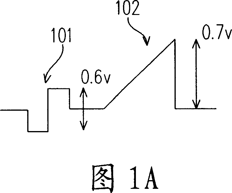
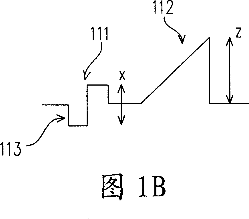
[0025] In the standard YPbPr signal, the Y signal representing the brightness (white level) is as shown in FIG. 1A , including a horizontal synchronization signal 101 and a data signal 102 . In a standard Y signal, the standard peak-to-peak voltage of the horizontal sync signal 101 is 0.6V, while the maximum peak-to-peak voltage of the data signal 102 is 0.7V, as shown in FIG. 1A . In practical applications, the Y signal is inevitably attenuated or amplified by the influence of the environment. As shown in FIG. 1B, the actual peak-to-peak voltage value of the horizontal synchronization signal 111 is X, while the maximum peak-to-peak voltage value of the data signal 112 is Z . The proportional relationship between X and Z is unchanged, that is to say, X / Z=0.6 / 0.7, and Z=X*0.7 / 0.6 ​​can be obtained after arrangement. Therefore, the present invention proposes a device and method that can adjust the voltage value of the data signal according to the horizontal synchronous signal. ...


PUM


Abstract

The invention relates to an analog YPbPr signal gain value regulating device and method. And the device comprises first clamper, analog digit converter and gain calculator, where the first clamper clamps the lowest level of horizontal synchronous signal of Y signal of an analog YPbPr signal to 0V; the analog digit converter converts the clamped Y signal from analog signal into digit signal to output; the gain calculator receives actual peak-to-peak voltage value of the horizontal synchronous signal from the analog digit converter to calculate and set the gain value of the analog digit converter.

Description

technical field [0001] The present invention relates to an analog YPbPr signal gain adjustment device and method, in particular to a high definition television (referred to as HDTV) analog YPbPr signal gain adjustment device and method. Background technique [0002] The front-end system of high-definition TV usually uses an analog-to-digital converter (abbreviated as ADC) to convert the analog YPbPr input signal. Environmental factors often cause the analog YPbPr input signal to be attenuated or amplified, thus making the digitized signal It cannot be extended to the maximum output range of the ADC, or it exceeds too much and becomes saturated, which affects the contrast of the picture. For example, when the maximum output range of the ADC is 00h-7Fh, the analog YPbPr input signal may only be converted to the range of 00h-5Fh due to attenuation, making the picture more dim, or converted to the range of 00h-9Fh due to amplification , causing the output to saturate. [0003]...

Claims


Application Information

Patent Timeline
IPC IPC(8): H04N9/64H04N11/24
Inventor 林裕人邱垂勋
Owner NOVATEK MICROELECTRONICS CORP
Why Eureka
Try Eureka