Electrode fused arc welding machine

A technology for arc welding machines and melting electrodes, which is applied to arc welding equipment, welding equipment, manufacturing tools, etc., can solve the problems of limiting arc ignition performance and insufficient rise of starting current, so as to improve arc ignition performance and prevent arcing Effect of cutting, preventing deterioration

Active Publication Date: 2011-04-13
DAIHEN CORP
View PDF1 Cites 0 Cited by
  • Summary
  • Abstract
  • Description
  • Claims
  • Application Information

AI Technical Summary

Problems solved by technology

Therefore, if a thyristor element is used, only the intermediate terminal of the reactor and the output terminal are short-circuited, and the rise of the starting current cannot be said to be sufficient due to the influence of the inductance value between the input terminal and the intermediate terminal of the reactor that is not short-circuited. , limiting the improvement in arc striking performance

Method used


Image

  • Electrode fused arc welding machine
  • Electrode fused arc welding machine
  • Electrode fused arc welding machine

Examples


Embodiment approach 1

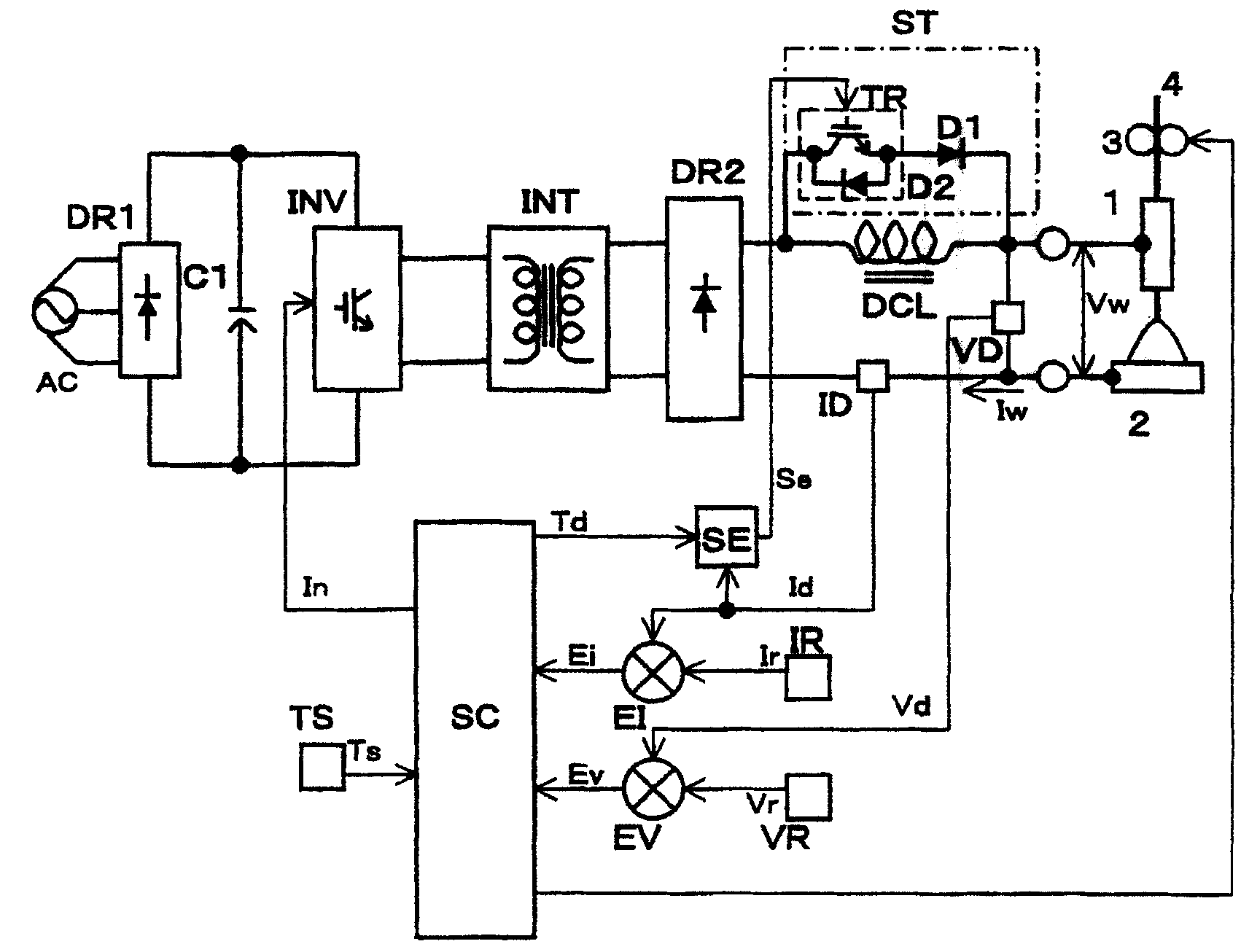
[0038] figure 1 It is an electrical connection diagram of the fusion electrode type arc welding machine according to Embodiment 1 of the present invention. In this figure, with Figure 6 The structural components with the same symbols in the electric connection diagram of the prior art fusion electrode arc welding machine shown in FIG.

[0039] exist figure 1 In the electrical connection diagram of the molten electrode arc welding machine shown, the arc starting circuit ST is formed by a switching element (such as an IGBT) TR and a diode D1, the input terminal of the reactor DCL is connected to the drain side of the switching element TR, and the output terminal Connect to the cathode side of diode D1. In addition, since the withstand voltage of the reverse voltage of the switching element (IGBT) is low, the protection diode D2 is generally provided inside the module. The reactor DCL is short-circuited or released only by the switching element TR, and the energy charged t...

Embodiment approach 2

[0055] Figure 4 It is a detailed diagram of the second arc striking control circuit SE2 related to Embodiment 2, in which, and figure 2 In the shown arc start control circuit SE of Embodiment 1, components with the same reference numbers operate in the same manner, and thus description thereof will be omitted, and only components with different reference numbers will be described.

[0056] Figure 4 The second arc striking control circuit SE2 shown in is composed of flip-flop circuit FF, current comparison circuit IC, reference current setting circuit IRF, second flip-flop circuit FF2, second current comparison circuit IC2, and second reference current setting The circuit IRF2 and the OR logic circuit OR are formed.

[0057] The second current comparison circuit IC2 compares the predetermined reference current setting value Irf2 with the welding current detection signal Id, and if it is higher than the second reference current setting value Irf2, the second current compari...

Embodiment approach 3

[0071] Figure 6 Electrical connection diagram of a molten electrode arc welding machine for AC pulsed MIG welding. In this figure, with figure 1 In the electrical connection diagram of the fusion electrode arc welding machine according to Embodiment 1 of the present invention shown, components with the same symbols operate in the same way, so descriptions are omitted, and only components with different symbols will be described.

[0072] Figure 6 The shown secondary-side inverter circuit INV2 is installed on the output side of the reactor DCL, so that the output smoothed to DC by the secondary rectification circuit DR2 and the reactor DCL operates at a low frequency (for example, 50 to 200 Hz) necessary for the AC pulse MIG , generating an AC arc.

[0073] Circuit configurations other than the secondary-side inverter circuit INV2 shown above, and figure 1 The electric connection diagram of the fusion electrode type arc welding machine related to Embodiment 1 shown has ...


PUM


Abstract

A consumable electrode-type arc welder supplies output between a consumable electrode and an object to be welded by a reactor provided in an output path in a welding power resource. The consumable electrode-type arc welder is provided with: an arc striking circuit which is series-connected with a source side of a switch member and an anode side of a diode, wherein an input terminal of the reactoris connected to the source side of the switch member, and an output terminal of the reactor is connected to a cathode side of the switch member; and an arc striking control circuit which turns on theswitch member when a welding start signal is inputted, and by which a large start current is passed between the consumable electrode and the object to be welded in a predetermined time, and then if electrification of the start current is finished, the start current is transfered to a small initial current, the switch membem is turned off when the initial current is passed. Thereby, even if an inductance of the reactor provided in the output path in the welding power resource is a big value, an arc striking performance is good.

Description

technical field [0001] The present invention relates to a fusing electrode type arc welding machine, and more particularly to a fusing electrode type arc welding machine which improves arc ignition performance at the start of welding. Background technique [0002] The arc ignition of the arc welding machine using the melting electrode generates a small arc while the melting electrode is in contact with the object to be welded, and the small arc grows and transfers to a stable welding arc. At this time, in order to perform arc ignition smoothly, it is necessary to make the rising speed of the starting current at the time of arc ignition very fast. [0003] Figure 7 Electrical connection diagram of a prior art fusion electrode arc welding machine for improved arc ignition. In this figure, the AC power source AC adopts a single-phase commercial AC power supply or a three-phase commercial AC power supply. The primary rectification current DR1 converts the AC voltage from the ...

Claims


Application Information

Patent Timeline
Patent Type & Authority Patents(China)
IPC IPC(8): B23K9/095B23K9/173B23K9/067
Inventor 西坂大志渡谷哲治
Owner DAIHEN CORP
Why Eureka
Try Eureka