Fluorescent lamp multi-station bridging apparatus
A multi-station, fluorescent lamp technology, used in manufacturing tools, glass molding, glass manufacturing equipment, etc., can solve the problems of occupying a lot of production space, reducing the accuracy of the butt, affecting the quality of the bridge, etc., to reduce the size and occupation. The effect of improving ground area, alignment accuracy, and saving motor power consumption
- Summary
- Abstract
- Description
- Claims
- Application Information
AI Technical Summary
Problems solved by technology
Method used
Image

Examples
Embodiment 1
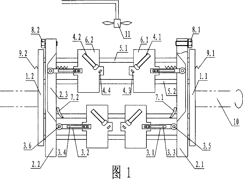
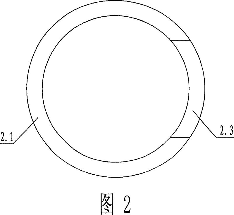
[0027] Embodiment 1: Referring to Figures 1 and 2, the multi-station bridging device for fluorescent lamps of the present invention includes a pair of side-by-side concentric turntables 1.1 and 1.2. Several pairs (such as 8 pairs) of circular guide rods 5.1 and 5.2, and bridging sliders 6.1 and 6.2 that are interspersed on the two guide rods and can slide axially. The circular guide rails 2.1 and 2.2 of the turntable have a section in the same position on the opposite surface of the guide rails, and there are slopes at both ends to connect the axially outward concave plane section 2.3 (the length depends on the number of melting burners and the bridge station). A lamp tube clamping device composed of spring pressing rods 4.1, 4.2 and corresponding fixed clamping dies 4.1, 4.2 is respectively arranged on the surface of each docking bridge slider. Each pair of slide blocks is also respectively provided with push rods 3.3 and 3.4 that make the bridge slide block close together; ...
Embodiment 2
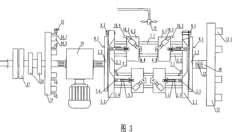
[0032] Embodiment 2: Referring to FIG. 3 , as in Embodiment 1, two side-by-side concentric rotating disks 1 are provided with follow-up parallel rotating disks 14 and 13 , as well as a power supply ring 16 and a rotating gas joint 17 . The lamp tube clamping device is a cylinder compression type lamp tube clamping device composed of fixed clamping molds 4.3 and 4.4 and telescopic cylinders 18.1 and 18.2, and the air cylinder is connected with air supply pipes 18.3 and 18.4 respectively. There are limit switches 14.1 and the same number of time relays 14.2 arranged on the circumference of the turntable 14 as the number of bridge sliders, and the turntable 13 is provided with the same number of solenoid valves 13.1. The rotating shaft 10 is a hollow shaft, and the conducting wire and air pipe 12 pass through the hollow shaft from one end to the other end. This device can realize full-automatic bridging operation (including unloading after bridging) in addition to manual loading....
Embodiment 3
[0034] Embodiment 3: As in Embodiment 1 or 2, the concave surface of the annular guide rail on one side, and the tension spring and push rod of the bridge slider on the same side are omitted, so that the side slider is fixed, and the opening and closing of the bridge slider, The sliding block on the other side is used to separate and close up to realize the bridge function.
PUM
 Abstract
Description
Claims
Application Information
 - R&D Engineer
- R&D Manager
- IP Professional
- Industry Leading Data Capabilities
- Powerful AI technology
- Patent DNA Extraction
Browse by: Latest US Patents, China's latest patents, Technical Efficacy Thesaurus, Application Domain, Technology Topic.
© 2024 PatSnap. All rights reserved.Legal|Privacy policy|Modern Slavery Act Transparency Statement|Sitemap