Drilling type well wall coring device

A technology of core extractor and borehole wall, which is applied in the direction of earthwork drilling, wellbore/well parts, etc., which can solve the problems of not accurately reflecting the original characteristics of the reservoir, high price, low power, etc., to reduce sticking in the well The risk on the wall, the safety of coring construction, the effect of large torque

Inactive Publication Date: 2007-09-19
陈为民 +5
View PDF0 Cites 28 Cited by
  • Summary
  • Abstract
  • Description
  • Claims
  • Application Information

AI Technical Summary

Problems solved by technology

Although this method obtains rock core method quickly, its shortcoming is as follows: (1) the danger of ground loading gun is big
(2) The core particles taken are small (ф10×10mm) and broken, destroying the original occurrence characteristics of the cores taken, and can only be used for qualitative analysis of the lithology, physical properties, and oil-gas properties of the reservoir , cannot accurately reflect the original characteristics of the reservoir
Foreign companies have done a lot of work in this area, such as Schlumberger, Halliburton, Atlas, etc. have developed corresponding instruments, but the application effect of these companies' instruments in domestic oil fields is relatively poor, and their shortcomings As follows: (1) The ground electrical control system is not intuitive and difficult to operate
(2) The motor power supply is unreasonable (110V single-phase power supply), and the power is small
(4) Unreasonable method for safe release of the instrument
(5) The repair and maintenance of the instrument is complicated, and the on-site usability is poor
(6) The core diameter (ф23mm) cannot meet the domestic core test analysis standard (ф25mm) (7) The price is expensive and the cost performance is poor

Method used


Image

  • Drilling type well wall coring device
  • Drilling type well wall coring device
  • Drilling type well wall coring device

Examples


Embodiment Construction

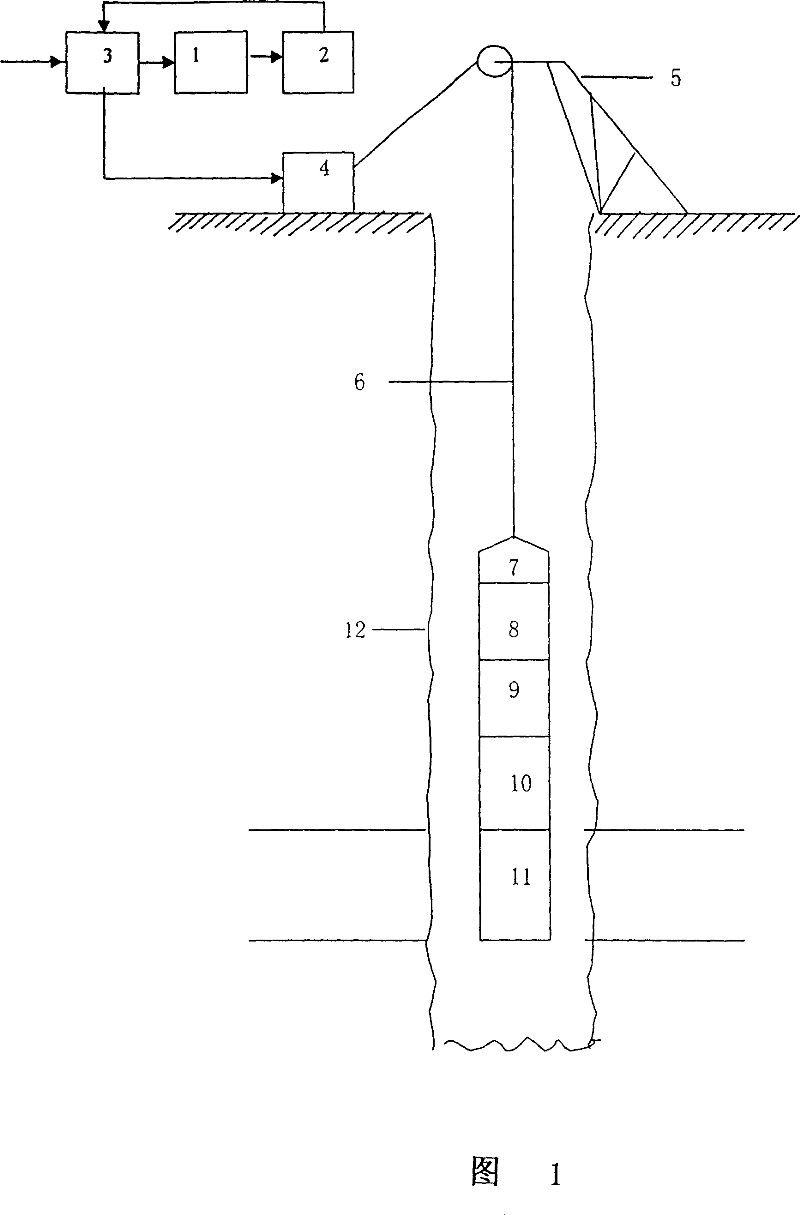
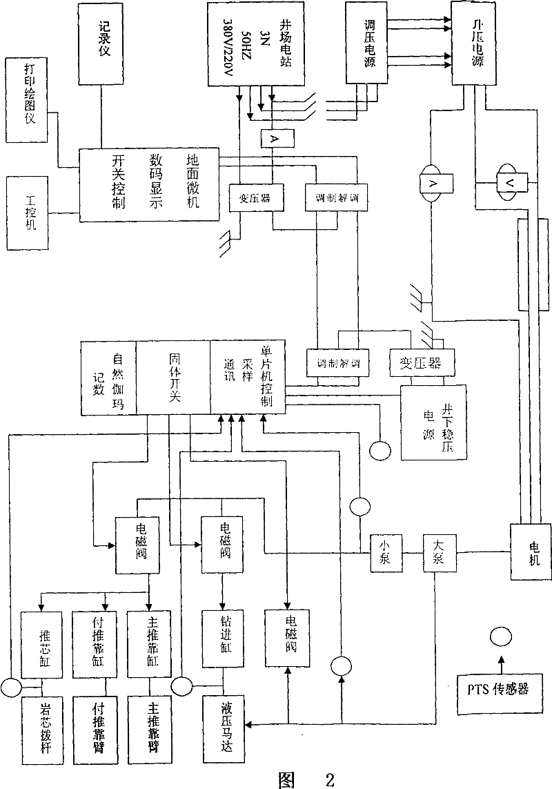
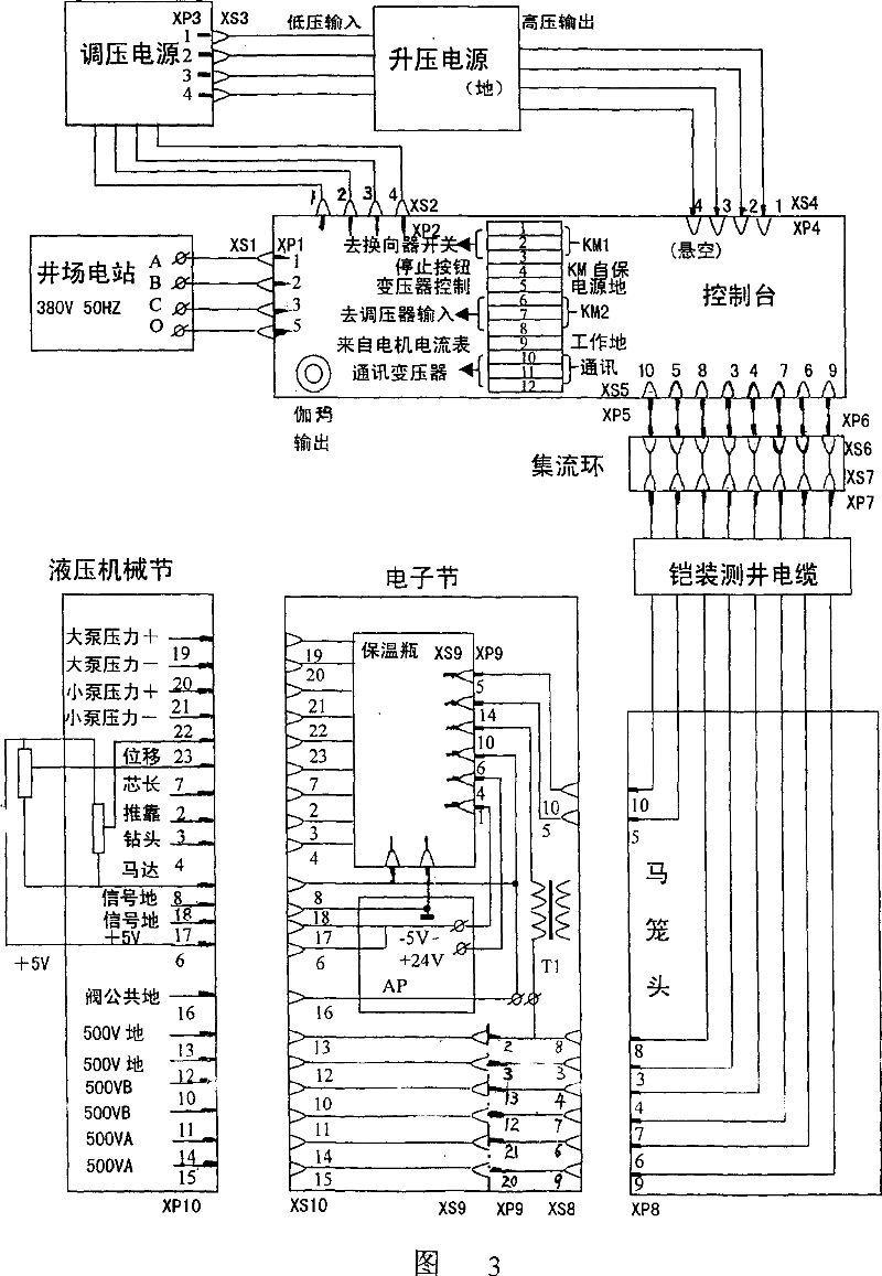
[0024] As shown in Figures 1, 2, and 3, the drilling-type borehole wall coring device disclosed by the present invention is mainly composed of two parts: the ground electrical control system and the downhole coring system; The ring and logging drawworks cables are connected to the downhole coring system.

[0025] The ground electrical control system is arranged on the ground, and it is mainly composed of a ground voltage regulating cabinet 1, a booster cabinet, 2 control cabinets 3, and a logging winch 4 (digital logging). Its main function is to provide power to downhole instruments, send out control signals, receive and process data fed back by various downhole sensors, and display and monitor the downhole coring system in real time. The ground electrical control system is connected to the collector ring through the collector ring cable, and the collector ring is connected to the downhole coring system through the logging cable 6 erected on the derrick 5 .

[0026] The down...


PUM


Abstract

The invention discloses a drilling type side-wall coring apparatus, which is consisted of ground electrical control system and down-hole coring system. The ground electrical control system is connected with the down-hole coring system by a high-voltage high-current collecting ring and a logging winder cable. The down-hole coring system is consisted of a halter, electron section, pressure balancing apparatus, hydraulic section and a mechanical section from above to below in series. The side-wall coring apparatus is put to down-hole by the logging winder cable, a natural gamma instrument is provided to trace and check depth of the same. When the coring object position is determined, signal is sent out by the ground electrical control system, and the down-hole coring instrument is driven to execute motions of pulling-against, drilling, core-folding, drilling back, stop pulling-against and core-storing. Meanwhile, real-time monitoring of instrument working condition and coring process are made by various sensing units, and recording data is transmitted to ground control system by the cable. Stratum core is acquired by side-wall vertically rotary drilling, which is accomplished by controlling down-hole instruments through the real-time digital display panel.

Description

technical field [0001] The invention relates to a borehole wall coring device, in particular to an open-hole well suitable for oil and gas exploration, which is lowered and positioned to the target layer by a logging winch cable, and is manipulated on the ground to perform rotary drilling on the borehole wall to obtain formations. A mechanical and electrical integration FCT type drilling type borehole wall coring device for rock core. Background technique [0002] In the process of oil exploration and development, drilling is the most direct and fundamental way to discover underground oil and gas reserves. Therefore, oil exploration and development companies have invested a lot of manpower and financial resources to carry out drilling work. In order to determine the nature and oil-gas content of the formation, a geophysical logging method has been developed, that is, to measure the electrical and physical properties of the formation along the well axis, and then through the...

Claims


Application Information

Patent Timeline
Patent Type & Authority Applications(China)
IPC IPC(8): E21B49/02
Inventor 陈为民刘中敏王建生班志强魏保明刘志仁
Owner 陈为民
Why Eureka
Try Eureka