Fine vacuum diaphragm pump

A diaphragm pump and high vacuum technology, applied in the field of diaphragm metering pumps and large hydraulic diaphragm pumps, can solve the problems of pump cavitation performance degradation, inlet pressure cavitation, exhaust pressure and flow instability, etc.

Active Publication Date: 2007-09-19
合肥华升泵阀股份有限公司
View PDF0 Cites 28 Cited by
  • Summary
  • Abstract
  • Description
  • Claims
  • Application Information

AI Technical Summary

Problems solved by technology

Because the pumping medium contains solid particles, the diameter of the delivery pipe is relatively small or the NPSH of the device is reduced due to the increase of the medium temperature; in addition, the high-temperature medium is easy to vaporize, so that the pressure in the pump chamber is lower than the vaporization pressure of the medium, making the pump steam The corrosion performance is greatly reduced, and the possibility of pump cavitation will also be greatly increased.
[0004] Diaphragm metering pumps used in petrochemical plants have problems such as unstable discharge pressure and flow rate, easy cavitation of pumps, easy blockage of inlet and outlet valve groups and channels, and cavitation problems that may occur when inlet pressure is too low under specific working conditions. It is a technical problem that enterprises and scientific research departments must solve
[0005] In the existing diaphragm metering pump, the diaphragm is fixed in the cavity between the liquid inlet and the liquid outlet in the pump body by a bracket. A vacuum liquid inlet and pressure discharge environment are formed between the ports. Since the liquid inlet end of the compensation valve communicates with the immersion chamber of the piston, the liquid outlet end communicates with the cavity between the diaphragm and the piston, so that when the piston moves outward A proper vacuum is formed between the diaphragm and the piston, and the hydraulic fluid to be metered enters the pump cavity. At this time, the process fluid in the immersion cavity enters the cavity between the diaphragm and the piston through the compensation valve and destroys the vacuum environment formed therebetween. Seriously affect the efficiency, stability and metering reliability of the diaphragm metering pump

Method used


Image

  • Fine vacuum diaphragm pump
  • Fine vacuum diaphragm pump

Examples


Embodiment Construction

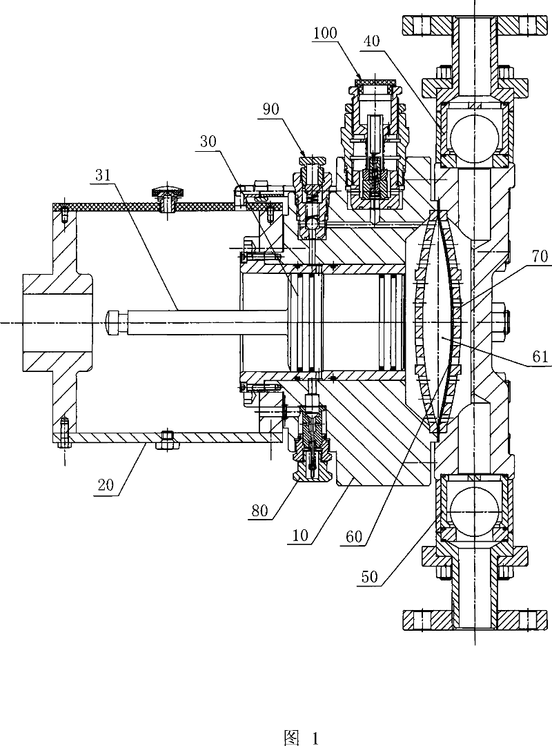
[0011] As shown in FIG. 1 , the high vacuum diaphragm pump disclosed in the present invention includes a cylinder block 10 and an oil pool cylinder 20. A piston 30 is located in the cylinder block 10, and a piston rod 31 of the piston 30 is located in the oil pool cylinder 20 and is submerged by the process fluid. , the cylinder 10 on the side of the piston 30 is provided with a pressure fluid inlet valve 40 and a liquid outlet valve 50, between which a diaphragm 60 and its fixing bracket 70 are arranged, the piston 30 is stepped, and the cylinder 10 has a The piston cavity of the piston 30 is matched with a piston ring on each diameter section of the piston 30 to cooperate with the piston cavity of the corresponding section, and the cylinder body 10 is also provided with a compensation valve 80 and an oil pressure control valve. Valve 90, the oil pool cylinder 20 is in one-way communication with the cavity between the piston 30 and the piston cavity through the compensation va...


PUM


Abstract

The invention relates to a high-vacuum diaphragm pump, stabilizing vacuum environment when the diaphragm pump is sucking hydraulic fluid and supplying pressure requirement when discharging hydraulic fluid, which comprises a cylinder body and a oil pool cylinder. The cylinder body is provided with a pressure-fluid inlet valve and an outlet valve, the diaphragm and a support bracket are provided between them, the said piston presents a echelonment shape, the oil pool cylinder communicates with a cavum between the piston and the piston cavity via a compensator valve, the cavum between the piston and the piston cavity communicates with the diaphragm oil pressure cavity via a pressure control valve. The invention can ensure reliability service of the pump while state of stable fine vacuum suction ability is maintained.

Description

technical field [0001] The invention relates to a high self-priming diaphragm metering pump, which is suitable for diaphragm metering pumps and large hydraulic diaphragm pumps. technical background [0002] In the prior art, the hydraulic end of the hydraulically driven diaphragm pump uses a diaphragm to separate the process fluid from the hydraulic fluid, and there is no leakage, so it has a wide range of applications. However, due to the large deformation stress of the diaphragm itself, the diaphragm material can be made of PTFE, synthetic Made of materials such as rubber and stainless steel, the fluid dynamic pressure energy that needs to be consumed is more. Compared with the plunger type liquid end, the inlet resistance of the hydraulically driven diaphragm metering pump becomes larger, and for the working conditions of poor suction conditions, high liquid viscosity and high temperature, because part of the energy of the hydraulic chamber sucked into the vacuum state is...

Claims


Application Information

Patent Timeline
Patent Type & Authority Applications(China)
IPC IPC(8): F04B43/067
Inventor 石海峡李强柴立平叶晓琰宫恩祥姜漫
Owner 合肥华升泵阀股份有限公司
Why Eureka
Try Eureka