Mounting apparatus
A mounting and surface plate technology, applied in the manufacture of electrical components, heat exchange equipment, semiconductor/solid-state devices, etc., can solve problems such as the weight of the top plate 1 and the prolonged heating and cooling time of the wafer
- Summary
- Abstract
- Description
- Claims
- Application Information
AI Technical Summary
Problems solved by technology
Method used
Image

Examples
no. 1 approach
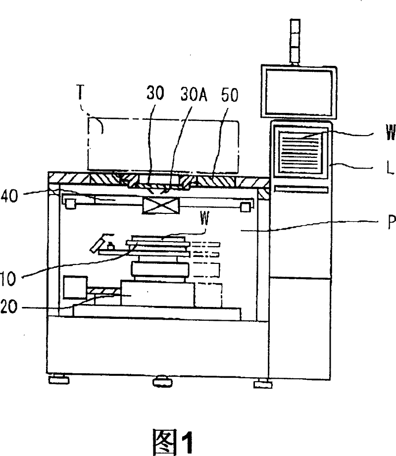
[0042] First, an inspection device to which the mounting device of this embodiment is applied will be described. This inspection apparatus includes, for example, as shown in FIG. Under the control of the device, the wafer W is transferred from the load chamber L to the probe chamber P, and after the electrical characteristics of the wafer W are inspected in the probe chamber P, the wafer W is returned to the original position.
[0043] As shown in FIG. 1 , the probe chamber P includes: a mounting device (wafer chuck) 10 that mounts a wafer W and can adjust its temperature; The XY stage 20; the probe card 30 arranged above the wafer holder 10 moved by the XY stage 20; Positioning mechanism 40 for accurate positioning of electrode pads.
[0044]In addition, as shown in FIG. 1 , a test head (test head) T of a tester (tester) can be rotatably arranged on the top plate 50 of the probe chamber P, and the test head T and the probe card 30 pass through the performance board (perform...
no. 2 approach
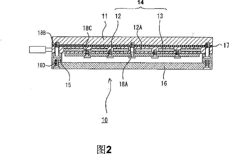
[0062] In the first embodiment, the flatness of the top plate can be improved, the thermal conductivity can be improved, the heating and cooling time of the object to be processed can be shortened, and the weight can be reduced. In the case of the mounting device 10 of the first embodiment, even if the temperature changes from +25°C to +150°C, the flatness of the top plate can be maintained at about 2.6 μm, which is significantly improved compared with the conventional 10 μm. The effect on thermal deformation was confirmed.
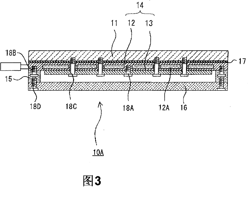
[0063] However, it has been found through subsequent experiments that, in the case of the mounting device 10 described above, the flatness of the top plate is affected by the bending of the lower parts, that is, the cooling jacket 12, the heat insulating ring 15, and the heat insulating plate 16, etc. during assembly. Influence, when the mounting device is assembled, the flatness of the top plate is reduced. The cooling jacket 12 and the heat insulating ...
no. 3 approach
[0073] As a result of studying the heating and cooling of the mounting devices 10 and 10B according to the first and second embodiments, not to mention the conventional mounting devices, it has been found that since the outer peripheral surfaces of components such as the top plate are exposed, even if the fastening of the top plate and the like is improved, In this method, due to disturbances such as heat dissipation from the outer peripheral surface of components such as the top plate and heat entering from the outside, the temperature of the outer peripheral portion of the top plate will drop or rise, etc., which will affect the inspection.
[0074] Therefore, in the present embodiment, a measure for suppressing the above-mentioned temperature change is sought by attaching the plate ring for heat preservation to the outer peripheral surface of the mounting device. Hereinafter, the placement device of this embodiment will be described with reference to FIG. 4 .
[0075] The m...
PUM
| Property | Measurement | Unit |
|---|---|---|
| Thermal conductivity | aaaaa | aaaaa |
Abstract
Description
Claims
Application Information
 - R&D
- Intellectual Property
- Life Sciences
- Materials
- Tech Scout
- Unparalleled Data Quality
- Higher Quality Content
- 60% Fewer Hallucinations
Browse by: Latest US Patents, China's latest patents, Technical Efficacy Thesaurus, Application Domain, Technology Topic, Popular Technical Reports.
© 2025 PatSnap. All rights reserved.Legal|Privacy policy|Modern Slavery Act Transparency Statement|Sitemap|About US| Contact US: help@patsnap.com