Catalyst deterioration detecting apparatus

A technology of degradation detection and catalyst, which is applied in the electronic control of exhaust treatment devices, diagnostic devices of exhaust treatment devices, exhaust treatment, etc., can solve the problems of deterioration of exhaust characteristics and time extension, and achieve the prevention of exhaust characteristics Effects of deterioration, prevention of HC and NOx emissions, and prevention of deterioration of exhaust characteristics

Inactive Publication Date: 2007-09-26
HONDA MOTOR CO LTD
View PDF1 Cites 17 Cited by
  • Summary
  • Abstract
  • Description
  • Claims
  • Application Information

AI Technical Summary

Problems solved by technology

Therefore, there is a problem of prolonging the time during which the exhaust gas characteristics deteriorate due to the deterioration detection.

Method used


Image

  • Catalyst deterioration detecting apparatus
  • Catalyst deterioration detecting apparatus
  • Catalyst deterioration detecting apparatus

Examples


no. 1 approach

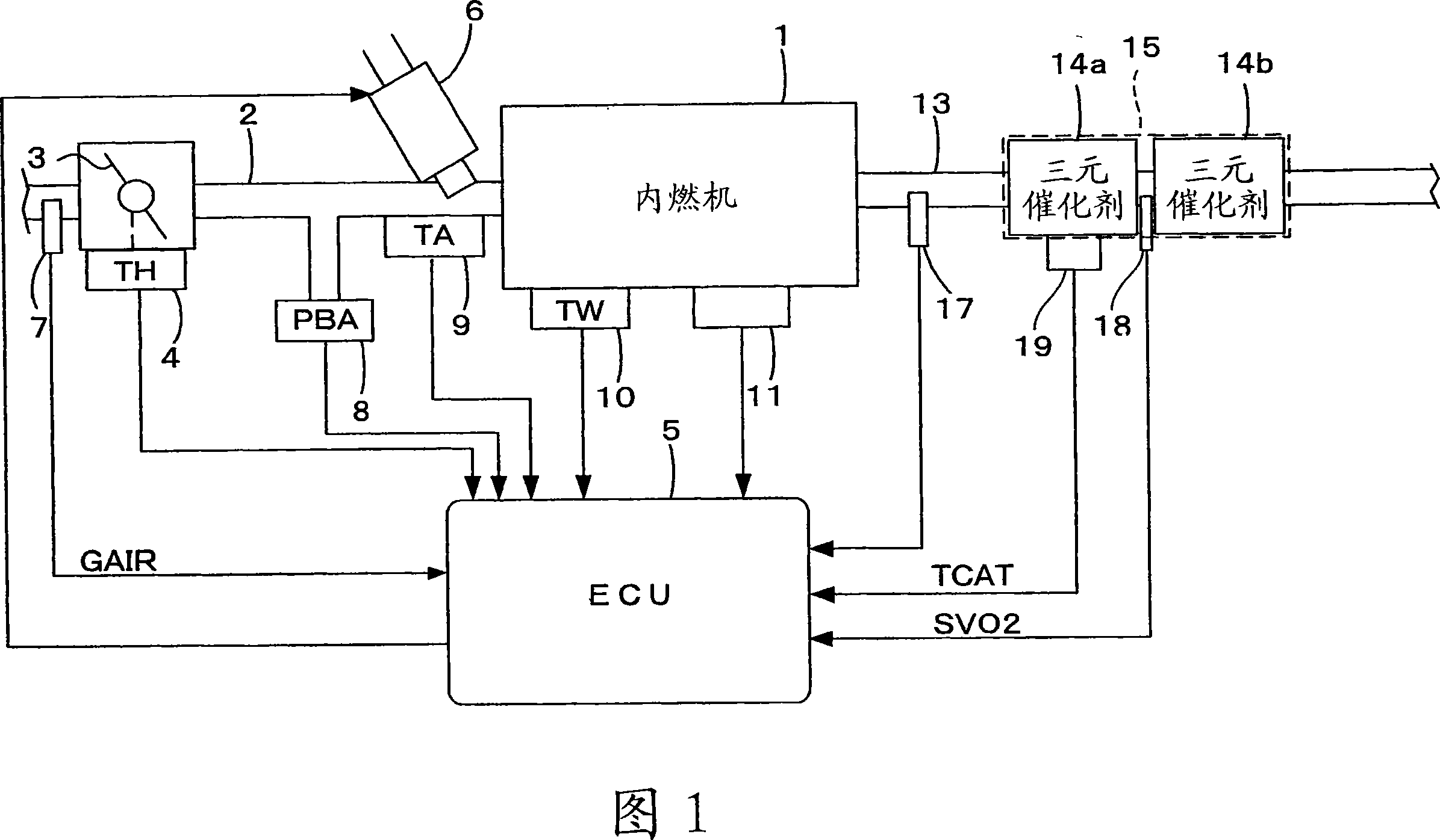
[0042] 1 is an overall configuration diagram of an internal combustion engine (hereinafter referred to as "engine") and its control device including a catalyst degradation detection device according to an embodiment of the present invention, and a throttle valve is arranged in the middle of an intake pipe 2 of, for example, a 4-cylinder engine 1. 3. A throttle opening (TH) sensor 4 is connected to the throttle valve 3 , outputs an electrical signal corresponding to the opening of the throttle valve 3 , and supplies it to an electronic control unit (hereinafter referred to as “ECU”) 5 .

[0043] The fuel injection valve 6 is provided for each cylinder between the engine 1 and the throttle valve 3 and slightly upstream of the intake valve not shown in the intake pipe 2, and each injection valve is connected to a fuel pump not shown in the figure, and It is electrically connected to the ECU 5 , and the opening timing of the fuel injection valve 6 is controlled based on a signal f...


PUM


Abstract

The invention provides a catalyst deterioration detection device, which almost cannot cause the depravation of discharge characteristics and can detect the deterioration degree of the catalyst with high precision. The oxygen amount (OS) flowing into a ternary catalyst (14a) can be calculated according to the detected intake air flow (GAIR) and the output of an oxygen concentration transducer (17) at an upstream side of the ternary catalyst (14a). The dense / thin switchover control (disturbance) of the air-fuel ration can be done as per the comparative result of the oxygen amount (OS) and a target value (OSOBJR and OSOBJL). If the air-fuel ratio of the output (SVO2) of an O2 transducer (18) at a downstream side changes in large range in the disturbance, the ternary catalyst (14a) is determined to be deteriorated. If the ternary catalyst (14a) is normal, the output of the O2 transducer is hardly changed through the setting of the target value (OSOBJR and OSOBJL) properly.

Description

technical field [0001] The present invention relates to a catalyst deterioration detection device for detecting the degree of deterioration of an exhaust gas purification catalyst provided in an exhaust system of an internal combustion engine. Background technique [0002] Conventionally, there is known a technique for determining the deterioration of an exhaust gas purifying catalyst (hereinafter simply referred to as "catalyst") provided in the exhaust system of an internal combustion engine. For example, Patent Document 1 discloses a device for measuring the first time CB and / or the second time CA, and judging catalyst degradation based on the first time CB and / or the second time CA, wherein the first time is From the moment when the air-fuel ratio of the air-fuel mixture supplied to the internal combustion engine is switched from the lean side to the rich side compared with the theoretical air-fuel ratio, the output change to the air-fuel ratio sensor (oxygen concentrati...

Claims


Application Information

Patent Timeline
Patent Type & Authority Applications(China)
IPC IPC(8): F02D45/00F02D41/14F01N11/00
CPCY02T10/47Y02T10/40
Inventor 末广幸夫饭田润
Owner HONDA MOTOR CO LTD
Why Eureka
Try Eureka