Check patentability & draft patents in minutes with Patsnap Eureka AI!

Reference voltage circuit

A voltage reference and circuit technology, applied in the direction of adjusting electrical variables, control/regulation systems, instruments, etc.

Inactive Publication Date: 2007-09-26
FARADAY TECH CORP
View PDF0 Cites 6 Cited by
  • Summary
  • Abstract
  • Description
  • Claims
  • Application Information

AI Technical Summary

Problems solved by technology

The positive temperature coefficient current generator is used to generate the positive temperature coefficient current

Method used


Image

  • Reference voltage circuit
  • Reference voltage circuit
  • Reference voltage circuit

Examples


Embodiment Construction

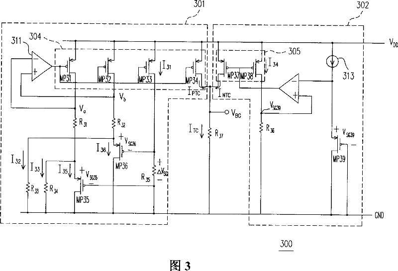
[0031] FIG. 3 is a voltage reference circuit according to an embodiment of the present invention, including a positive temperature coefficient current generator 301 , a negative temperature coefficient current generator 302 , and a resistor R37 . The outputs of the positive temperature coefficient generator 301 and the negative temperature coefficient generator 302 are both connected to the ground terminal through the resistor R37. The positive temperature coefficient generator 301 is used to generate the positive temperature coefficient current I PTC , and the negative temperature coefficient current generator 302 is used to generate the negative temperature coefficient current I NTC . After the two currents I PTC and I NTC Synthesizes a temperature-independent current I TC , this current I TC will flow through the resistor R37 to form a stable reference voltage V with low temperature dependence BG .

[0032] The positive temperature coefficient current generator 301 i...


PUM


Abstract

This invention relates to one voltage reference circuit, which comprises positive temperature parameter current generator, negative temperature current generator and first resistance, wherein, the positive parameter current generator has two transistor operations areas and the second resistance is connected between two transistor tubes; the second resistance uses operation in weak reverse areas transistor with similar double electrode transistor property to generate positive temperature parameter current; negative temperature parameters current generator is on third one through the negative one to generate negative temperature parameter current.

Description

technical field [0001] The present invention relates to a voltage reference circuit, and in particular to a voltage reference circuit of a CMOS transistor. Background technique [0002] FIG. 1 is a graph of parameters related to semiconductor process technology. As the channel length of MOS (metal-oxide-silicon) transistors shrinks, the critical voltage V of MOS transistors TH and did not increase with the operating voltage V DD proportional decrease. Therefore, under the condition of limited voltage headroom, all analog circuits are faced with how to operate at a low operating voltage V DD However, the original performance of the circuit is still maintained. [0003] Figure 2 is a circuit diagram of a traditional voltage reference circuit, which uses PMOS transistors MP21 and MP22 biased in the subthreshold region, successfully exchanging a larger voltage headroom, allowing the circuit to work at a low operating voltage V DD Down. The traditional voltage reference cir...

Claims


Application Information

Patent Timeline
IPC IPC(8): G05F3/30
Inventor 王为善张坤山陈美秀
Owner FARADAY TECH CORP
Features
  • R&D
  • Intellectual Property
  • Life Sciences
  • Materials
  • Tech Scout
  • Unparalleled Data Quality
  • Higher Quality Content
  • 60% Fewer Hallucinations
Learn More