

High-frequency power amplifier
A power amplifier and power amplifying technology, applied in high frequency amplifiers, power amplifiers, improving amplifiers to reduce temperature/power supply voltage changes, etc., can solve the problem of increasing the memory of cellular phone terminals, increasing the loading area of cellular phone terminals and their costs and other problems to achieve the effect of stable output power characteristics
- Summary
- Abstract
- Description
- Claims
- Application Information
AI Technical Summary
Problems solved by technology
Method used
Image

Examples
no. 1 example
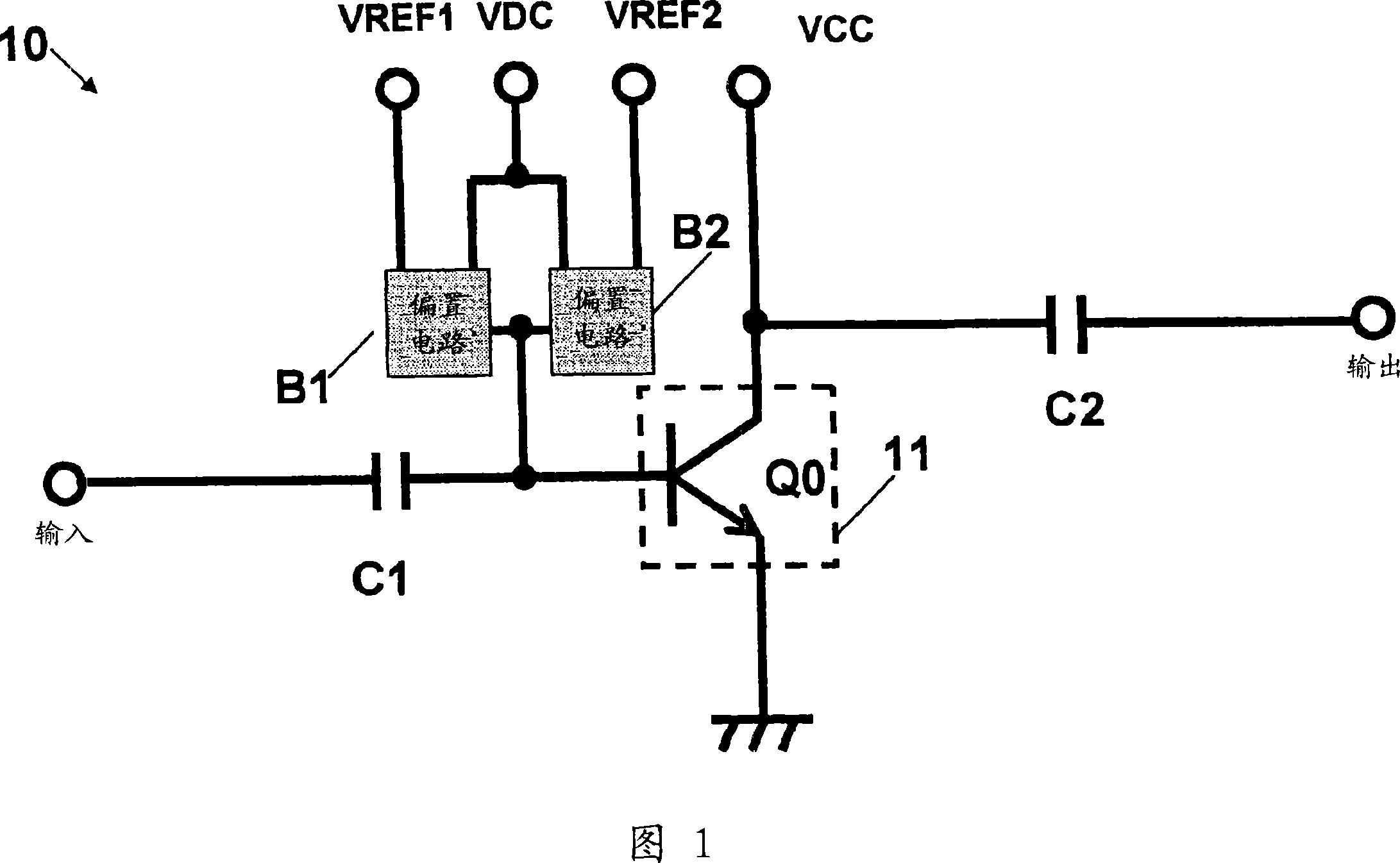
[0061] 1 to 3 are diagrams each showing an example of a circuit configuration of a high-frequency power amplifier 10 with a temperature compensation function according to a first embodiment of the present invention. Now, a description will be given of the structure and operation of a high-frequency power amplifier 10 according to a first embodiment of the present invention with reference to FIGS. 1 to 6 .
[0062]In FIG. 1, a high frequency power amplifier 10 includes an RF amplifier 11, a high power output bias circuit B1, a low power output bias circuit B2, and capacitors C1, C2. The high-frequency signal is connected to the base of the power amplifying transistor Q0 of the RF amplifier 11 through the capacitor C1. The reference voltage application terminal VREF1 and the reference voltage application terminal VREF2 are connected to the base of the power amplifying transistor Q0 of the RF amplifier 11 through the high power output bias circuit B1 and through the low power out...
no. 2 example
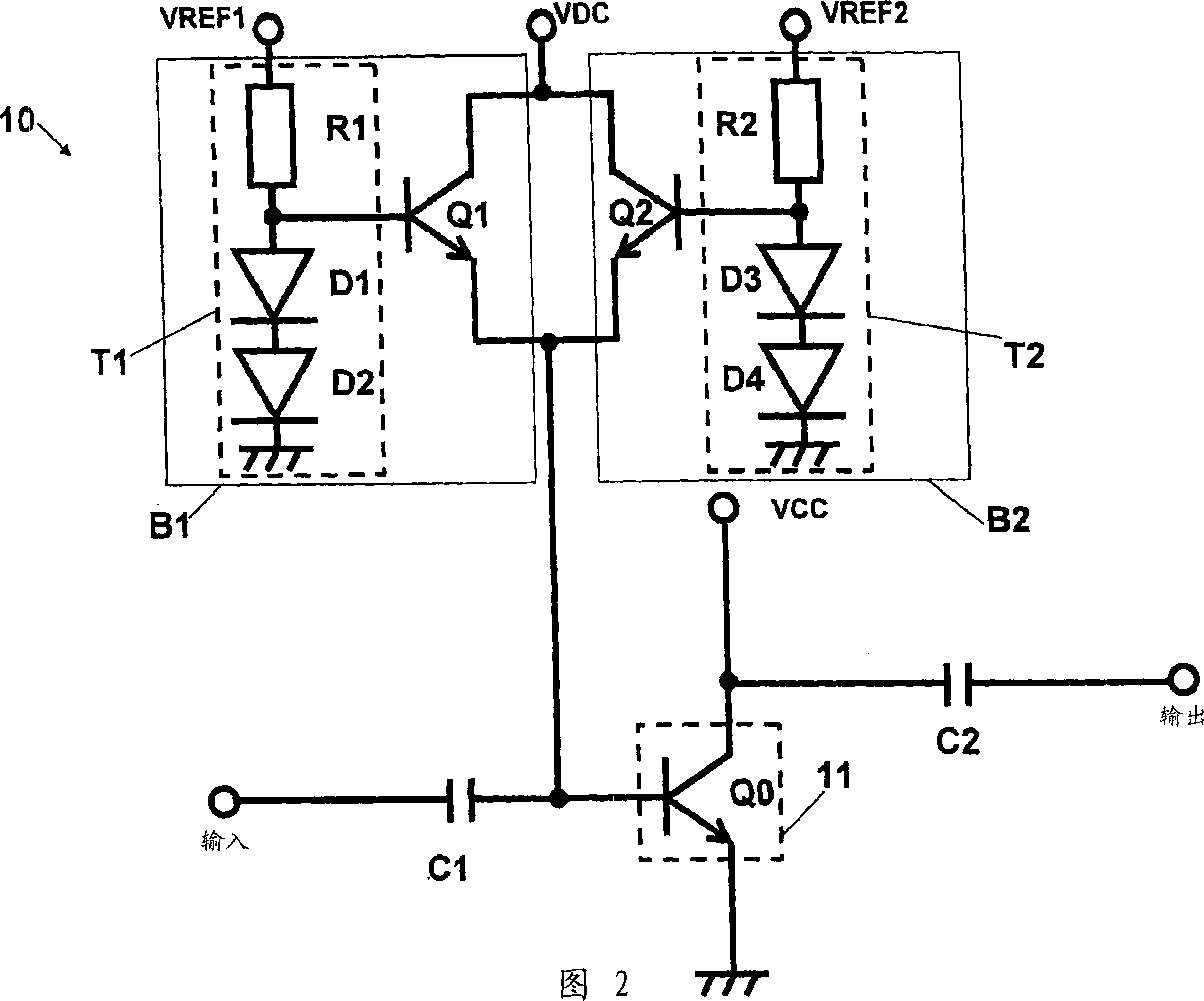
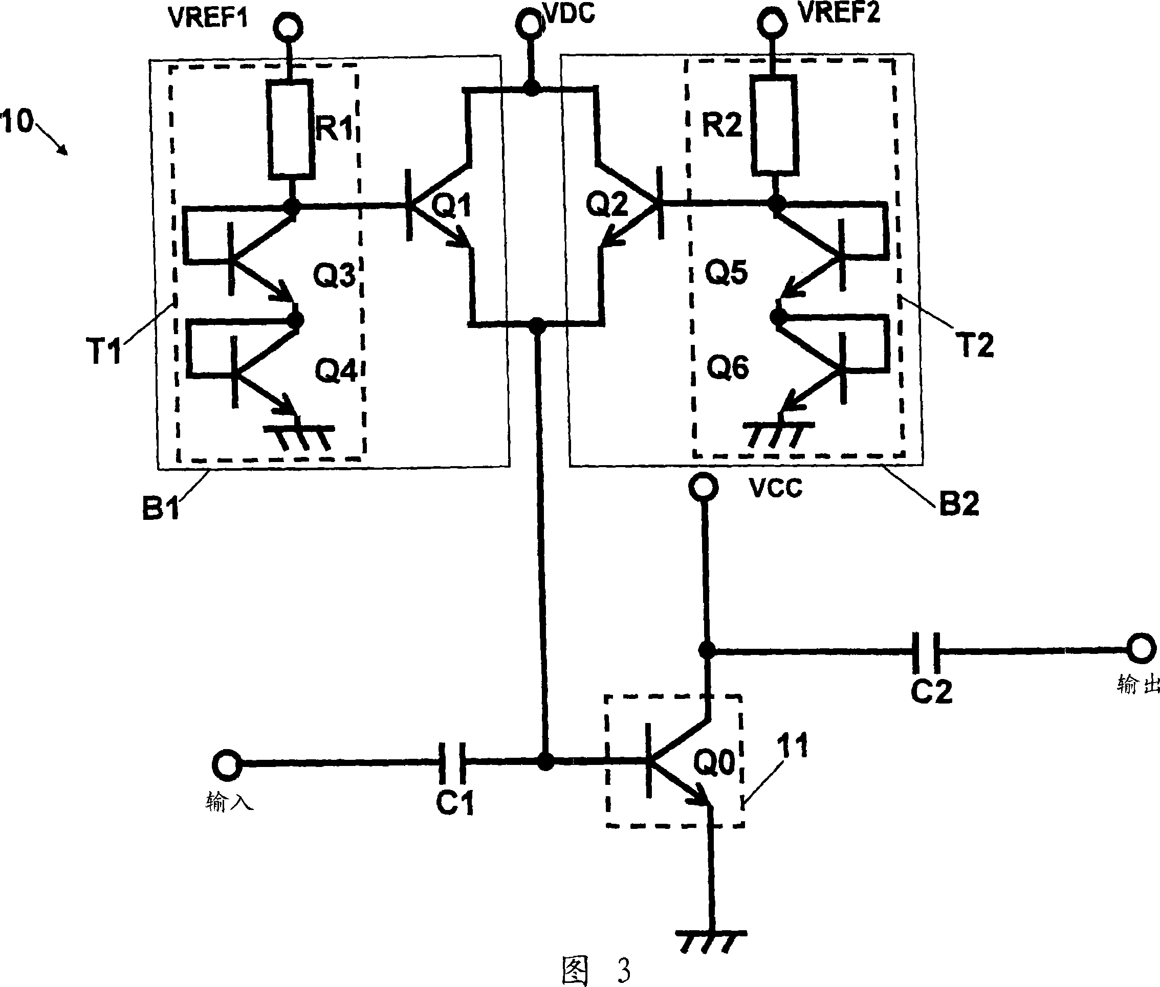
[0091] In the structure discussed in the high-frequency power amplifier 10 according to the first embodiment described above, the temperature compensation circuit T1 is used for the high-power output bias circuit B1, and the temperature compensation circuit T2 is used for the low-power output bias circuit B2, respectively. . These temperature compensation circuits T1 and T2 are configured by connecting resistors (R1 and R2) in series with cascade-connected two-stage transistors (Q3, Q4 and Q5, Q6), while applying reference voltages VREF1 and VREF2 to the temperature-compensated circuits T1 and T2.
[0092] However, since the reference voltage is generated by a DA converter made using Si-IC, in practice, the reference voltage is provided with a variation of the order of ±3%. Here, assuming that the reference voltage VREF is set to a voltage of 2.8V, it is presumed to vary within the range of 2.716V to 2.884V. In the variation range of 2.716V to 2.884V of the reference voltage...
no. 3 example
[0113] In the structure described for the high-frequency power amplifier 10 according to the first embodiment described above, the temperature compensation circuit T1 is provided in association with the high-power output bias circuit B1, and the temperature compensation circuit T1 is provided in association with the low-power output bias circuit B2. The temperature compensation circuit T2; applies the reference voltages VREF1 and VREF2 to these temperature compensation circuits T1 and T2; and applies the voltage of the bias voltage terminal VDC to the bias transistors Q1 and Q2 in common. The current flowing in the VDC terminal increases as the output power increases, and at the time of output power of 28 dBm, a current of about 5 mA flows.
[0114] However, in order for the high-frequency power amplifier 10 to actually start operating, it is necessary to control the control voltages VREF1, VREF2, and VDC according to such a timing chart as shown in FIG.
[0115] That is, in o...
PUM
 Abstract
Description
Claims
Application Information