
Bus groove transmission device and multi-layer bus groove electric connection method

A technology of power transmission device and busway, which is applied to the installation of circuit devices, conductive connections, and busbars. It can solve problems such as automatic stoppage, burnout of conductors, and increased costs, so as to reduce manufacturing costs and avoid excessive current. The effect of simplifying the installation process

Inactive Publication Date: 2007-10-03
珠海光乐电力母线槽有限公司
View PDF3 Cites 20 Cited by
  • Summary
  • Abstract
  • Description
  • Claims
  • Application Information

AI Technical Summary

Problems solved by technology

However, this busway structure needs to be provided with special side plates to form the line grooves for installing control lines, which increases the cost. Moreover, the side plates used in this patent must be fixed together with the busway during assembly. Therefore, After the bus duct is installed on the building, it is more difficult to arrange the control lines in the duct
[0007] Moreover, the electrical connection method between two adjacent multi-layer bus ducts in the prior art is to electrically connect each conductor of each group of conductors in the corresponding layer, but such a connection method makes each group The conductors used to transmit the same-phase current are connected on different levels to form separate transmission lines. When the resistance of these transmission lines is different, the current on the transmission line with smaller resistance will be too large during the transmission process. Therefore, it is easy to burn out the layer of conductor with less resistance or must automatically stop working because of too high temperature
Therefore, with this connection method in the prior art, the maximum current of the entire busway can only be about 2000 amperes. With the continuous increase of electricity demand, the carrying capacity of this busway can no longer meet the demand

Method used


Image

  • Bus groove transmission device and multi-layer bus groove electric connection method
  • Bus groove transmission device and multi-layer bus groove electric connection method
  • Bus groove transmission device and multi-layer bus groove electric connection method

Examples


Embodiment 1

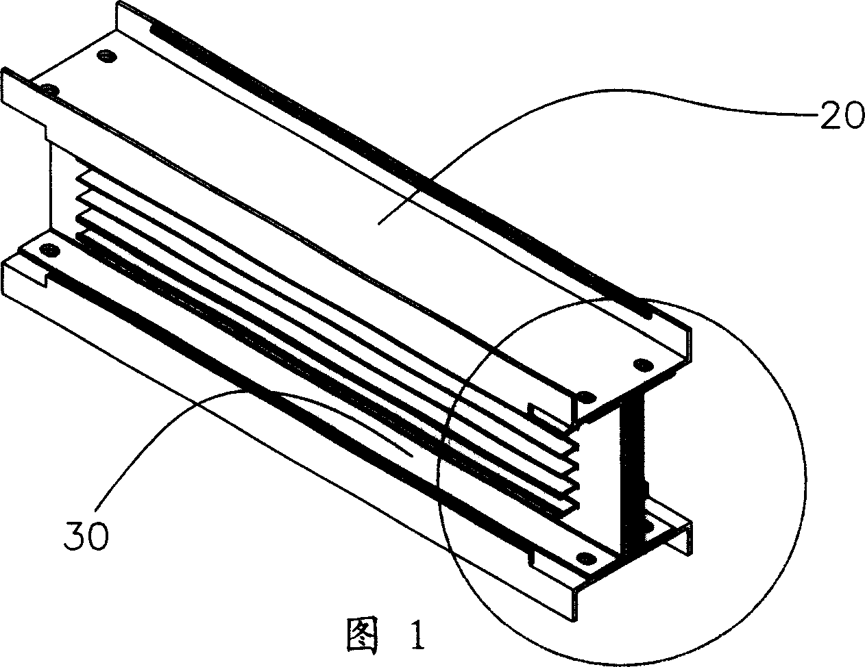
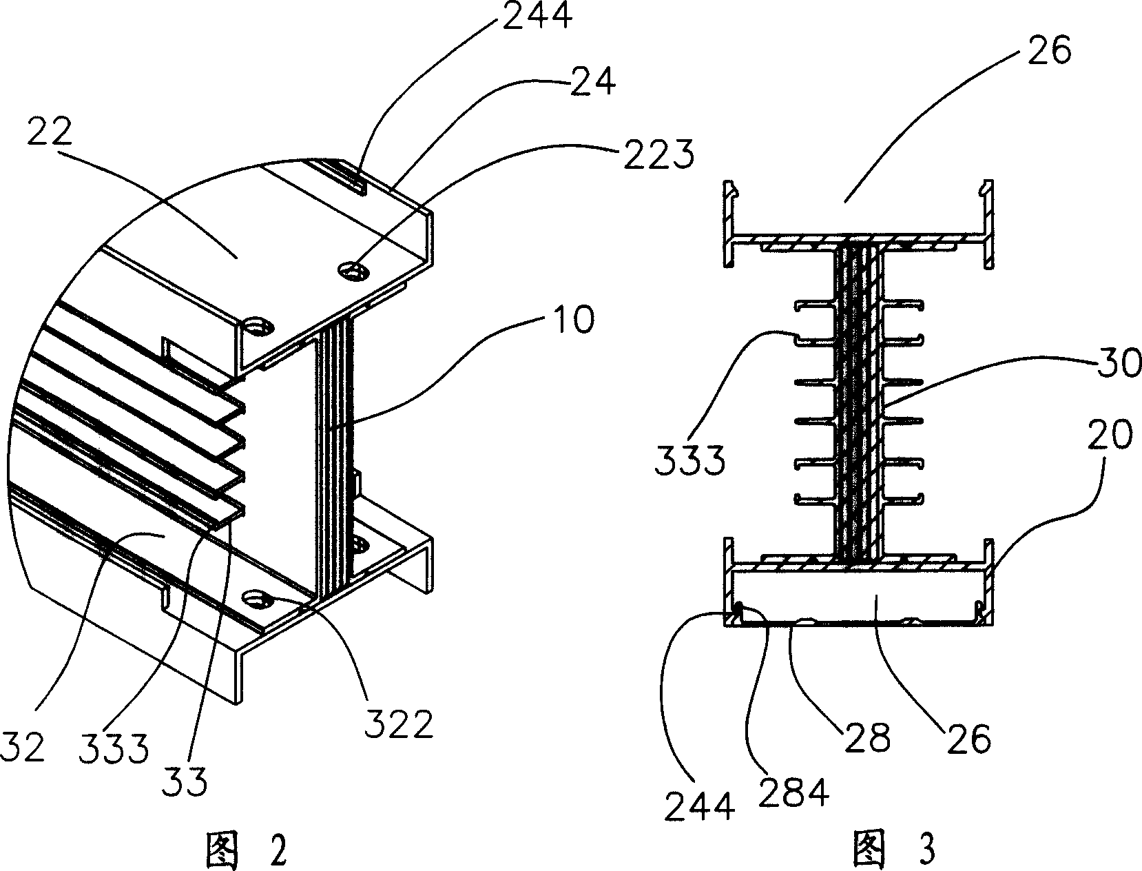
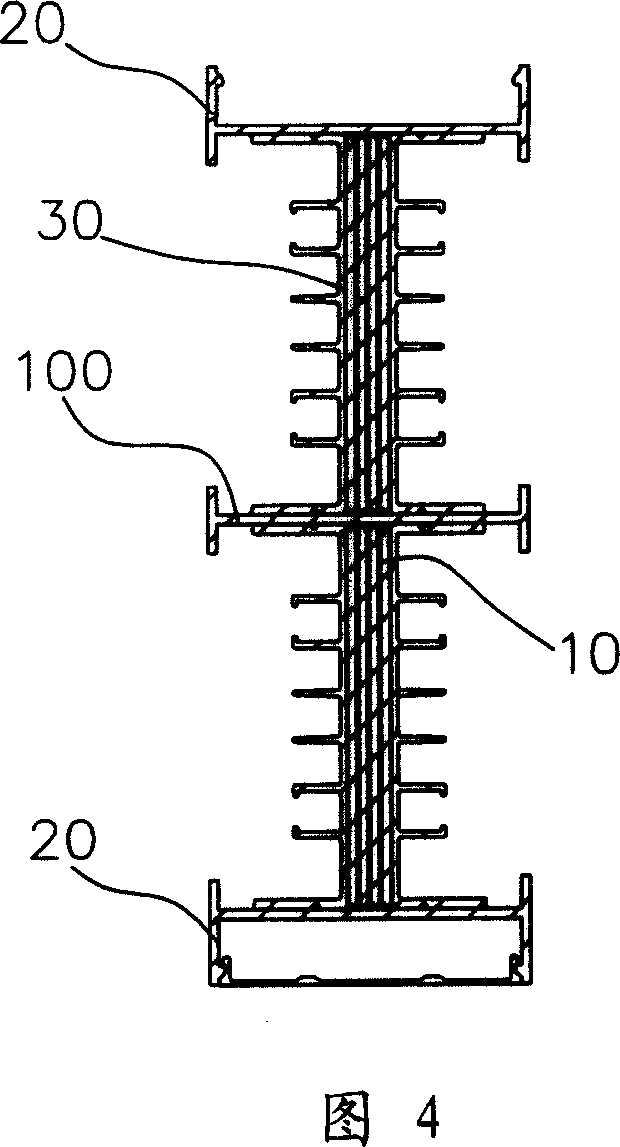
[0031] Please refer to Figure 1 to Figure 3, the bus duct power transmission device of the present invention includes multiple dense bus ducts in this embodiment, here we first introduce the single-layer bus duct with simple structure as an example, in which the bus duct is used to install A set of mutually insulated conductors 10, such as conductive copper bars, is provided. In this embodiment, the set of conductors 10 includes four conductive copper bars. The busway includes a pair of cover plates 20 and a pair of side plates 30 , and the conductor group 10 is installed in the space enclosed by the pair of cover plates 20 and the pair of side plates 30 .

[0032] A pair of cover plates 20 are symmetrical in shape, and one of them will be introduced here. The cover plate 20 is roughly U-shaped, including a body 22, and a pair of side walls 24 extend upwards from the two side edges of the body 22 to form a measurement and control wire slot 26, for laying out measurement and co...

Embodiment 2

[0046] As another embodiment of the present invention, the bus duct power transmission device of the present invention can adopt other types of bus ducts, such as air-type bus ducts, high-performance bus ducts, fire-resistant bus ducts, waterproof bus ducts, and air additionally insulated bus ducts Groove, high-voltage co-phase closed bus duct, etc.

[0047] Cover plate 20, side plate 30, connecting cover plate 40, connecting side plate 50 all can adopt asymmetric shape, such as, can only have the side plate 30 of one side to be provided with heat sink 33 structures, can only have the cover plate 20 of one side to be provided with There are 26 structures for measuring and controlling wire slots.

[0048] At least one hook member 60 can be arranged in each buckle slot 525 , and the hook member 60 can be directly fixed on the side plate 30 by other means, such as buckle, riveting, welding and so on.

[0049] The slot cover 28 can be pivotally connected to the measurement and co...


PUM


Abstract

A bus-bar frame of power transmission device is prepared as forming said bus-bar frame by a pair of covering plates and two pairs of side plates, setting two sets or above of conductor groups at space enclosed by said covering plates and side plates in lamination mode. The method for electric-connecting multilayer bus-bar frame is also disclosed.

Description

technical field [0001] The invention relates to a power supply equipment, in particular to a bus duct power transmission device for power transmission. Background technique [0002] With the rapid development of the city, there are more and more high-rise buildings, and the power load of the buildings has increased sharply. The original wires and cables have been gradually replaced by large-capacity due to their small capacity, inconvenient branching, and inconvenient cluster management. , convenient branching, and convenient cluster management instead of bus ducts. [0003] However, there are also some disadvantages in the busway. For example, if the insulation and sealing effect of the connecting device between the busway is not good, it will cause leakage accidents, resulting in casualties or fires. Moreover, the heat dissipation problem of the bus duct has always been a big problem for the research and development personnel of the bus duct. Once the high temperature gen...

Claims


Application Information

Patent Timeline
Patent Type & Authority Applications(China)
IPC IPC(8): H01R9/00H02G5/00H02J3/00
Inventor 郑光乐
Owner 珠海光乐电力母线槽有限公司
Learn More