Spiral support and manufacturing method thereof

A technology of helical and tubular materials, applied in the field of tubular helical stents, can solve the problems of high cost, complex structure and disconnection of the helix, and achieve the effects of avoiding energy loss, simple manufacturing technology and uniform connection.

Active Publication Date: 2007-10-03
蒂科电子雷切姆有限责任公司
View PDF8 Cites 1 Cited by
  • Summary
  • Abstract
  • Description
  • Claims
  • Application Information

AI Technical Summary

Problems solved by technology

[0008] A problem with known helical stents is that the connections between the individual loops are structurally complex and expensive and / or the edges are not evenly firmly connected to each other
Uneven connection of the edges causes the necessary release force to manually unfold the extruded body to fluctuate greatly, so separation of the connected edges when releasing the helical stent becomes difficult or impossible manually or the helix breaks

Method used


Image

  • Spiral support and manufacturing method thereof
  • Spiral support and manufacturing method thereof
  • Spiral support and manufacturing method thereof

Examples


Embodiment Construction

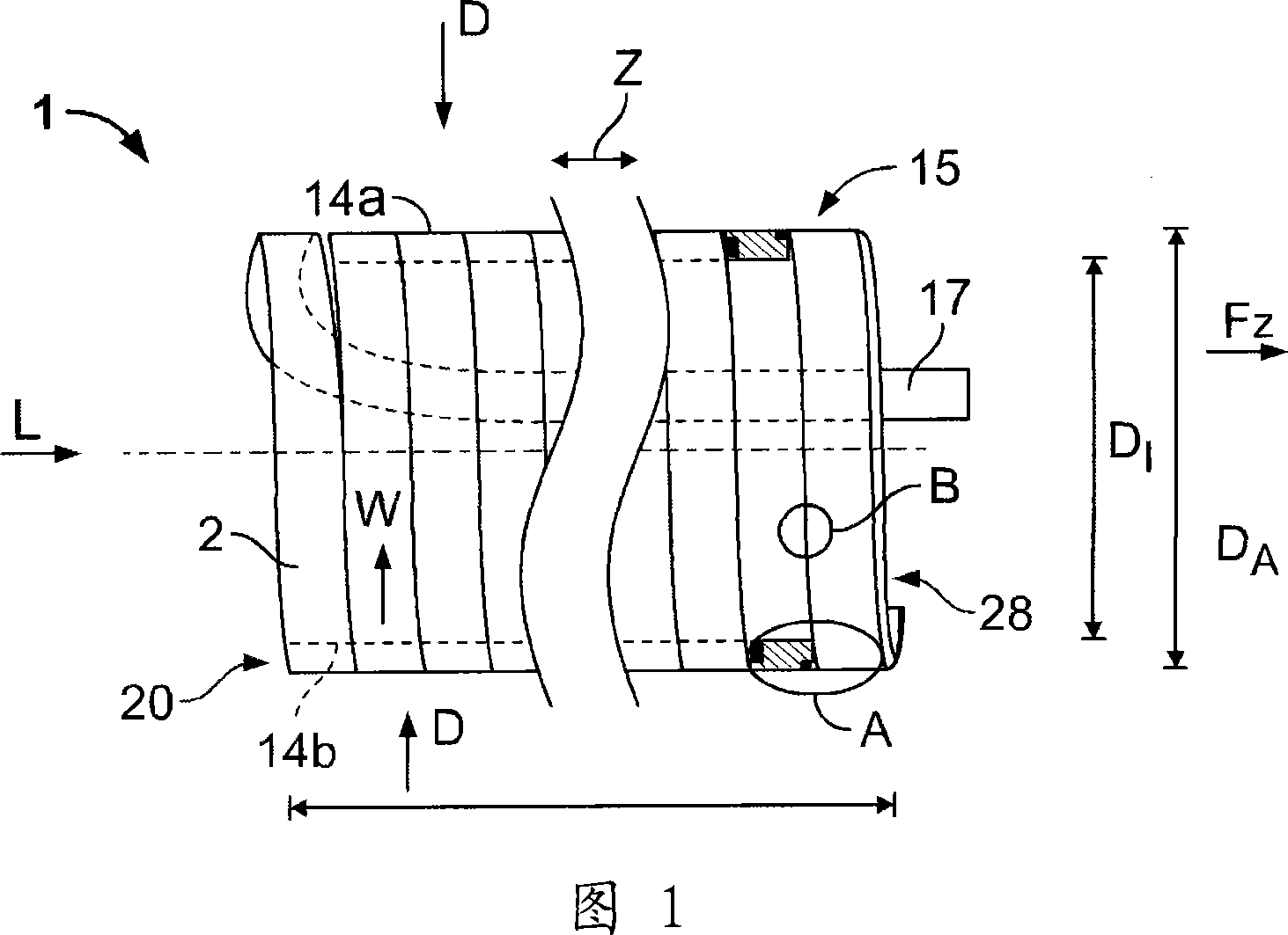
[0043] First, the general configuration of the helical stent 1 according to the present invention will be described with reference to FIGS. 1 and 2 and the exemplary embodiment shown therein.

[0044] The helical support 1 consists of an extruded body 2 wound in a winding direction W with a plurality of loops 15 .

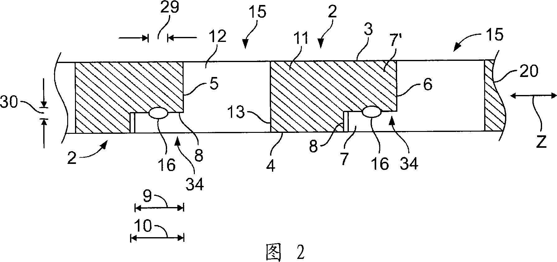
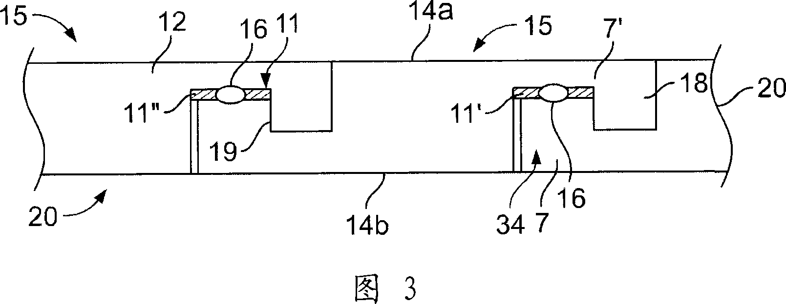
[0045] The extruded body 2 is configured as a substantially continuous strip-shaped body, which is produced, for example, by an extrusion method. In this way, theoretically, the helical stent 1 can be manufactured to an infinite length. In practice, the helical stent 1 is usually about 30 to 50 cm long. In cross section, the extruded body 2 is substantially rectangular in the embodiment shown in FIGS. 1 , 2 and 9 , with parallel upper and lower edges 3 , 4 and shorter side edges 5 , 6 . The side edges 5, 6 match each other. The rectangular protrusion 7 is arranged on the edge 6 side, and the rectangular groove 8 is arranged on the edge 5 side. The protrusion 7 ...


PUM


Abstract

The invention relates to a tubular helical support (1) for the radial support of elastically expanded tube material (26) and a method for the production thereof. The helical support (1) is constructed of at least one extruded body (2) wound to form several windings (15), the edges (5, 6) of which are connected to one another in the longitudinal direction (L) of the helical support (1) at least in portions. In order to provide a helical support (1) which reliably withstands the pressure forces of the expanded tube material (26) and which can easily be removed from the tube material (26), it is provided according to the invention that the edges (5, 6) are connected to one another by at least one laser weld seam (16).

Description

technical field [0001] The invention relates to a tubular helical stent for radially supporting elastically expandable tubing, comprising at least one extruded body wound to form a plurality of loops, the edges of which are helically helical at least in certain regions. The longitudinal directions of the supports are connected to each other. Background technique [0002] Helical supports of this type are known in the art and are used to hold tubing, such as for example insulating tubes and sleeve bodies, in an expanded state prior to assembly. Insulation tubes are used in electrical engineering such as, for example, cable splices or cable plug-in connectors for the electrical insulation and sealing of electrical components. Since high voltages, for example above 100 kv, may be applied to these elements, the insulating tube is constructed with thick walls and made of a material with good electrical insulating properties, such as silicone. In the assembled state, the insulat...

Claims


Application Information

Patent Timeline
Patent Type & Authority Applications(China)
IPC IPC(8): H02G15/18H02G3/04H02G1/14H01R4/70H01R43/00H01B17/58
CPCB29C65/1451B29C66/21B29C65/1664B29C65/1635B29C65/1432B29C66/52272B29C65/1658B29C66/4329H02G1/14B29C66/83415B29C66/232B29C65/1677B29C66/83413B29C66/221B29C66/24249B29C65/16B29C66/1142B29C65/1683B29C66/4322B29C66/3032H02G15/1833B29C66/12841B29L2023/00B29C66/1282B29C53/78B29C61/065B29C66/24241B29C66/49B29C66/73921B29K2995/0027Y10T428/139B29C66/30321B29C66/30325
Inventor 西洛·西蒙森
Owner 蒂科电子雷切姆有限责任公司
Why Eureka
Try Eureka