Yarn heating device

A technology for heating devices and filaments, which is applied in the direction of electric heating devices, heat treatment of artificial filaments, electric/magnetic/electromagnetic heating, etc. It can solve the problem of lowering the fixed vibration frequency, not being able to thicken the drive shaft to increase rigidity, and the difficulty of high-speed rotation of the main body of the roller. And other issues

Inactive Publication Date: 2007-10-10
TMT MACHINERY INC
View PDF1 Cites 9 Cited by
  • Summary
  • Abstract
  • Description
  • Claims
  • Application Information

AI Technical Summary

Problems solved by technology

This point is due to the structure of the above-mentioned patent document 1, the above-mentioned connection part and the boss part are arranged on the front end side of the drive shaft, and the length of the drive shaft has to be increased during multi-head winding.
Also, since the center of gravity of the roller is located away from the connection portion and the hub portion as the connection portion and the hub portion are arranged on the tip side, the fixed vibration frequency of

Method used


Image

  • Yarn heating device
  • Yarn heating device
  • Yarn heating device

Examples


Embodiment Construction

[0023] Embodiments of the invention will be described below with reference to FIGS. 1 to 3 .

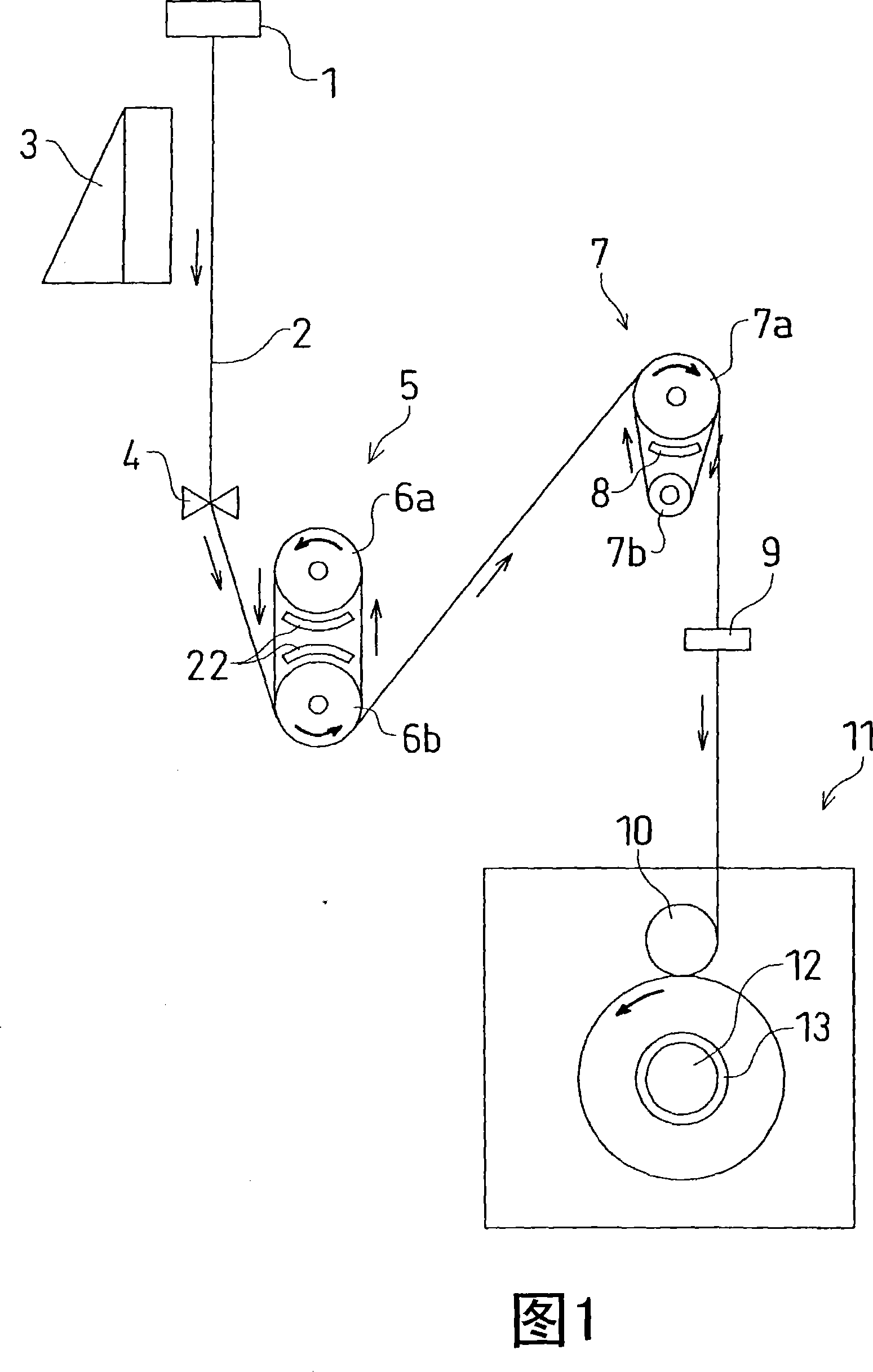
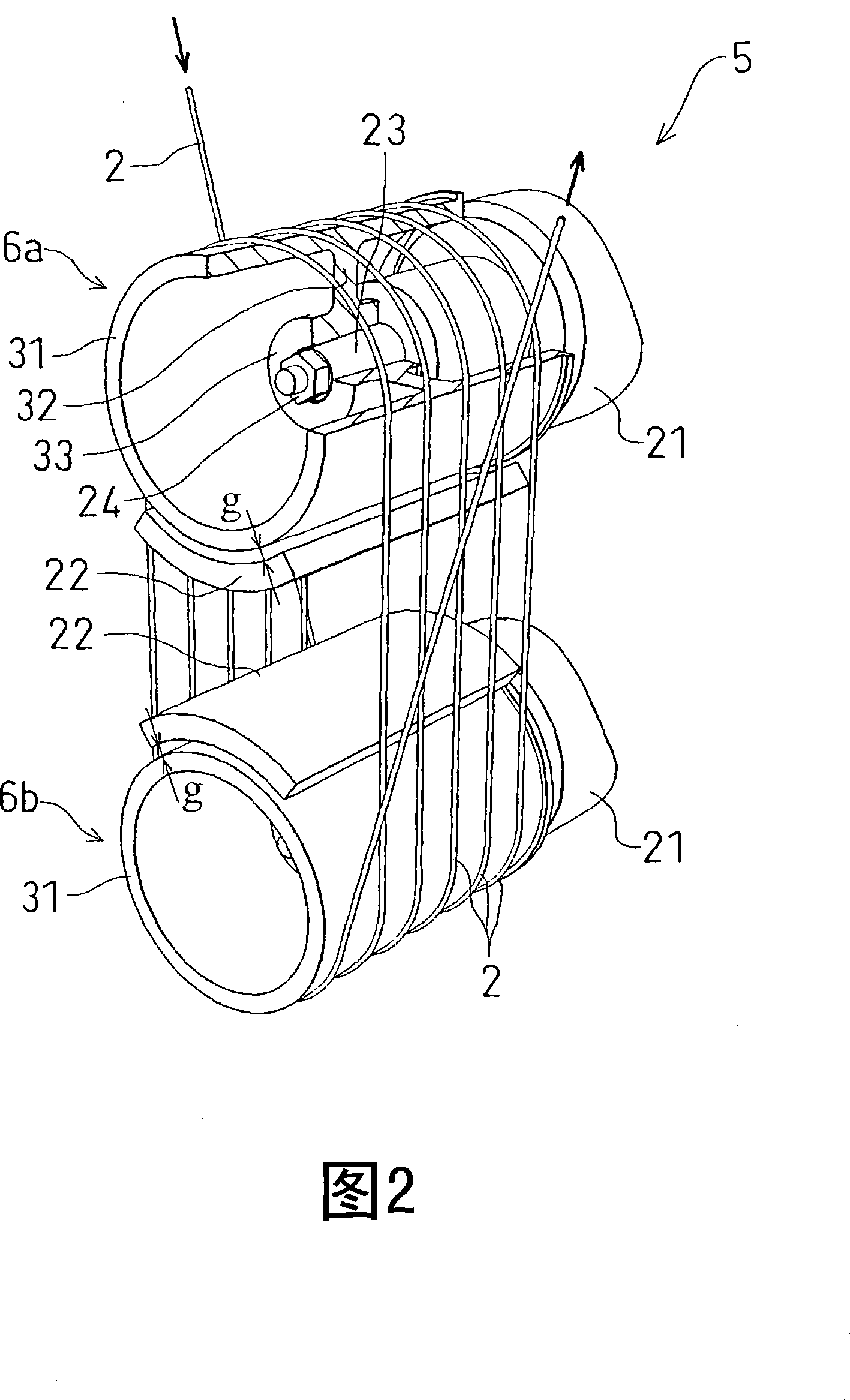
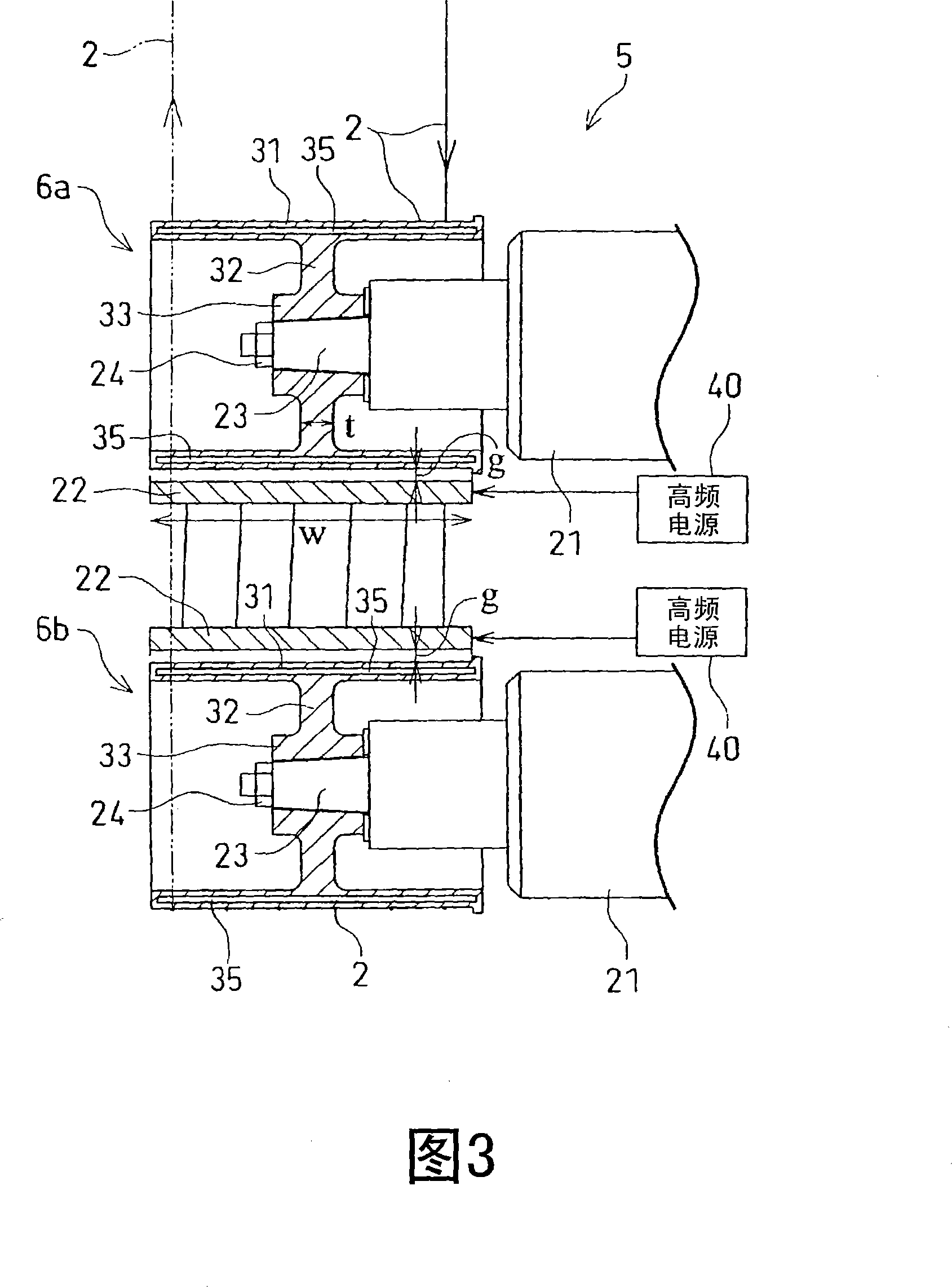
[0024] Fig. 1 shows the overall configuration of a spinning and drawing device (manufacturing device for synthetic fiber yarn) equipped with a yarn heating device 5 according to the present embodiment. In this spinning drawing device, the filament (yarn) 2 in the state of molten polymer ejected from the spinneret 1 is cooled and solidified by the wind blown out from the cooling device 3, and is sent to the yarn heating device 5 through the oiling device 4. . The yarn heating device 5 is configured to include two rollers 6a, 6b arranged one above the other and driven by motors, and the yarn 2 is wound around these rollers 6a, 6b to be heated. The detailed structure of the yarn heating device 5 will be described later.

[0025] On the downstream side of the yarn heating device 5, a drawing roll 7 including a main roll 7a and an auxiliary roll 7b is provided. The main roller 7a is dr...


PUM


Abstract

An object of the present invention is to provide a structure of a yarn heating device suitable for a high-speed heat processing of a yam. The yarn heating device (5) comprises rollers (6a and 6b) which a yarn (2) is wound around, induction heating coils (22 and 22) as a heating means, and electric motors (21 and 21) for driving to rotate the rollers (6a and 6b). Each of the rollers (6a and 6b) includes a cylindrical portion (31) which the yarn (2) is wound around and a flange portion (32) for connecting the cylindrical portion (31) with an output shaft (23) of the electric motor (21). The induction heating coil (22) is disposed outside each of the rollers (6a and 6b), and each of the rollers (6a and 6b) is heated by the induction heating coil (22) to heat the yarn (2).

Description

technical field [0001] The present invention relates to the structure of a yarn heating device which winds a yarn around the peripheral surface of a roller and heats it. Background technique [0002] As such a yarn heating device, there is, for example, the device disclosed in Patent Document 1 (Japanese Patent Application Laid-Open No. 2000-256936 (Fig. 1, 0011, 0014). The yarn heating device in this Patent Document 1 is equipped with a drive The hub portion at the top end of the shaft and the cylindrical roller body portion integrally connected to the hub portion by a disc-shaped connection portion (flange portion) form a cantilever-supported roller body portion by the connection portion. The state is mounted on the front end side of the above-mentioned driving shaft. In addition, a heater is installed on the radially inner side of the above-mentioned roller main body, and the roller main body is heated by receiving heat from the heater. [0003] In recent years, there ha...

Claims


Application Information

Patent Timeline
IPC IPC(8): D01D10/02D02J13/00
CPCD02J13/005D01H13/28H05B6/107H05B6/145
Inventor 中川理
Owner TMT MACHINERY INC
Why Eureka
Try Eureka