Friction reducing and shock reducing automatic rotary device for oil well pole
An automatic rotation, oil well rod technology, applied in drill pipe, drilling equipment, earthwork drilling and other directions, can solve the problems of poor wear balance, affect production efficiency, reduce oil production and other problems, and reduce maintenance wells Second, the effect of reducing the cost of comprehensive oil production and improving the liquid production of oil wells
- Summary
- Abstract
- Description
- Claims
- Application Information
AI Technical Summary
Problems solved by technology
Method used
Image
Examples
Embodiment 1
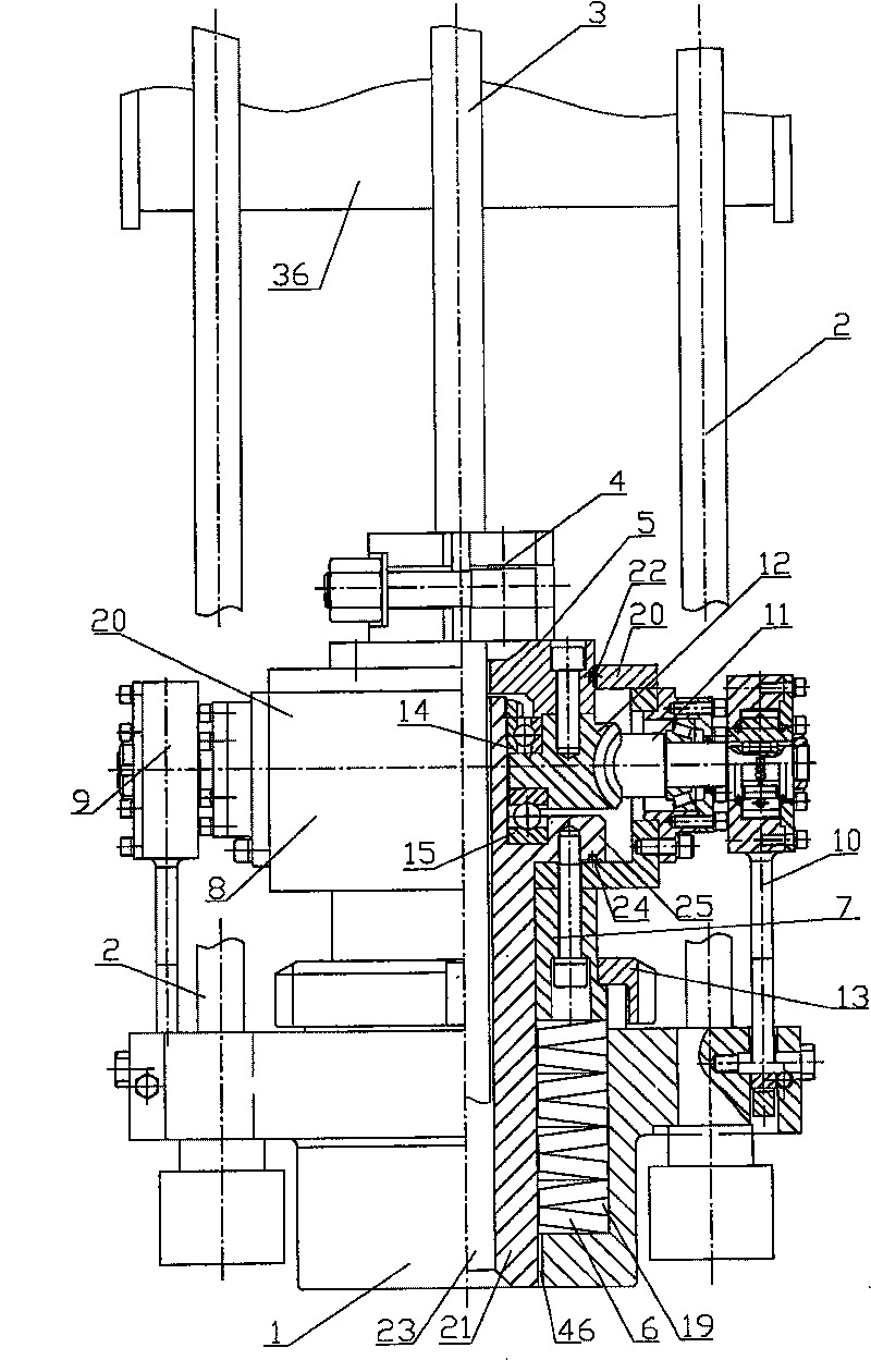
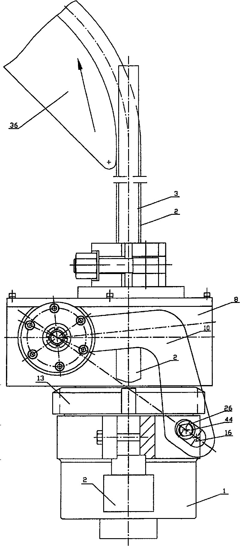
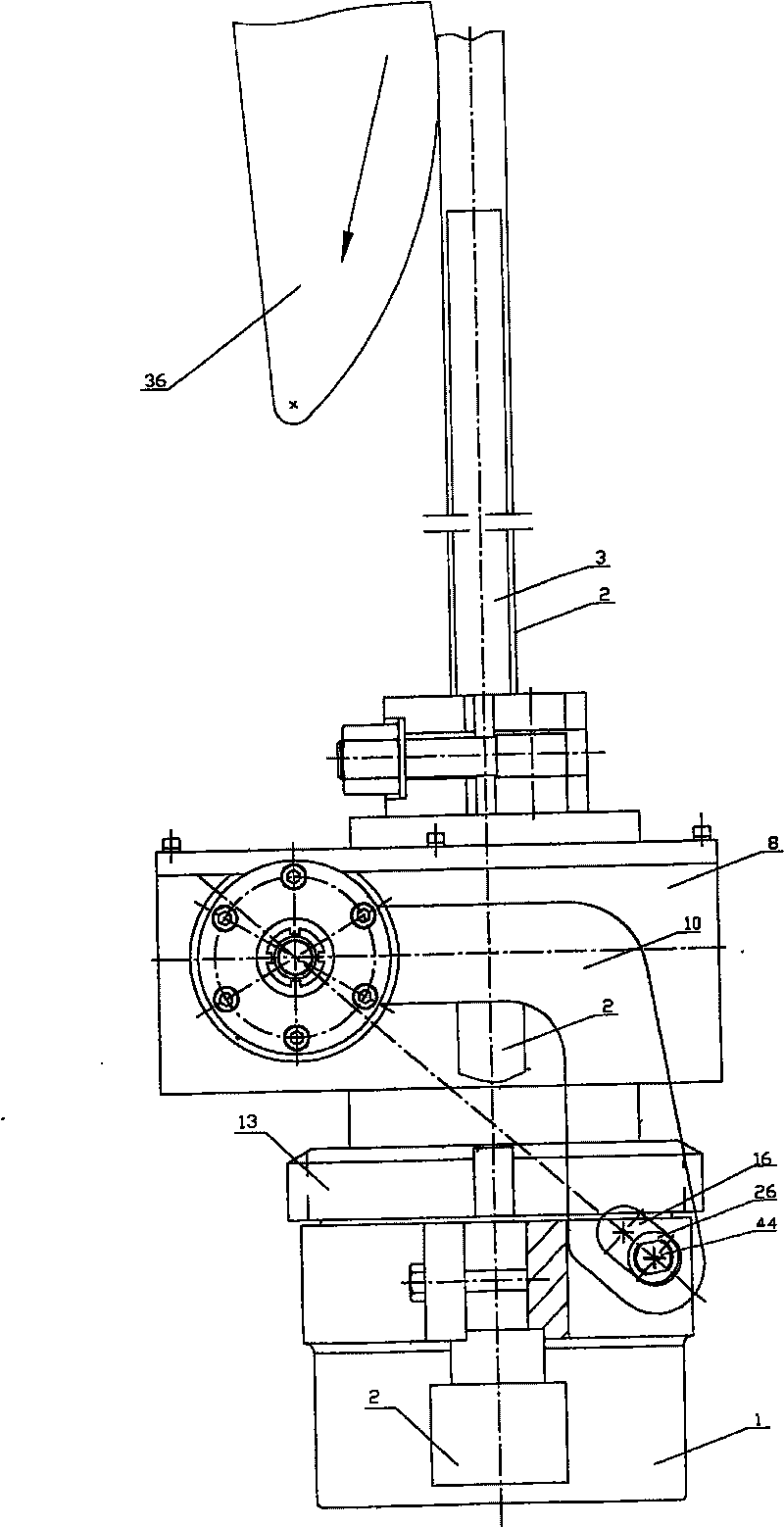
[0023] control figure 1 , figure 2 , image 3 , The device of the present invention is mainly composed of a rotator housing 1, a disc spring 6, a piston 7, a reducer 8, a one-way clutch 9, and a square card holder 5. Two braids 2 are connected to the housing 1 respectively, so that the device of the present invention is hoisted on the donkey head 36 of the pumping unit by the braids 2 . The oil well rod string 3 is clipped to the square clamp 4, and the square clamp 4 is supported on the square clamp 5. The housing 1 is provided with a cylindrical chute hole 19 , and the front end of the piston 7 slides into the chute hole 19 . A disc spring 6 is installed under the piston 7 in the chute hole 19, and the rear end of the piston 7 is connected to the lower part of the reducer casing 20, and the two are connected as one by bolts. Under the elastic force of 6, move up and down along the chute hole 19 together.
[0024] The speed reducer 8 is a worm gear reducer, and its outp...
Embodiment 2
[0032] This embodiment is basically the same as the previous embodiment, except that the structure of the swing rod is different, and the rod of the swing rod faces upwards to connect with the reducer 20. Please refer to Figure 6 , Figure 7 , Figure 8 .
[0033] One end of the rod part of the swing rod is connected with the guide rod 33 through the guide sleeve 32, and the guide rod 33 is sleeved in the guide sleeve 32, so that the connection position of the swing rod and the guide rod can be adjusted. After adjustment, the guide sleeve 32 is fixed on the on the guide rod 33. One end of the guide rod is connected with a push rod 35 perpendicular thereto, and the front end of the push rod is hinged with rollers 34. The limit plate 17 is connected to the upper side of the reducer casing, and the limit plate 17 is used to limit the fork 10 when it rotates. The torsion spring 18 is sleeved on the torsion spring pin 45 of the limiting plate 17 , one end of which is fixed on ...
PUM
 Abstract
Description
Claims
Application Information
 - R&D
- Intellectual Property
- Life Sciences
- Materials
- Tech Scout
- Unparalleled Data Quality
- Higher Quality Content
- 60% Fewer Hallucinations
Browse by: Latest US Patents, China's latest patents, Technical Efficacy Thesaurus, Application Domain, Technology Topic, Popular Technical Reports.
© 2025 PatSnap. All rights reserved.Legal|Privacy policy|Modern Slavery Act Transparency Statement|Sitemap|About US| Contact US: help@patsnap.com


