Fibre-optical with high wide-band and manufacturing method thereof

A manufacturing method and high-bandwidth technology, applied in manufacturing tools, glass manufacturing equipment, optics, etc., can solve the problems of increasing processing time and increasing processes

Inactive Publication Date: 2007-10-10
STERLITE OPTICAL TECH
View PDF1 Cites 2 Cited by
  • Summary
  • Abstract
  • Description
  • Claims
  • Application Information

AI Technical Summary

Problems solved by technology

The increase in the number of steps in the manufa

Method used


Image

  • Fibre-optical with high wide-band and manufacturing method thereof
  • Fibre-optical with high wide-band and manufacturing method thereof
  • Fibre-optical with high wide-band and manufacturing method thereof

Examples


example 1

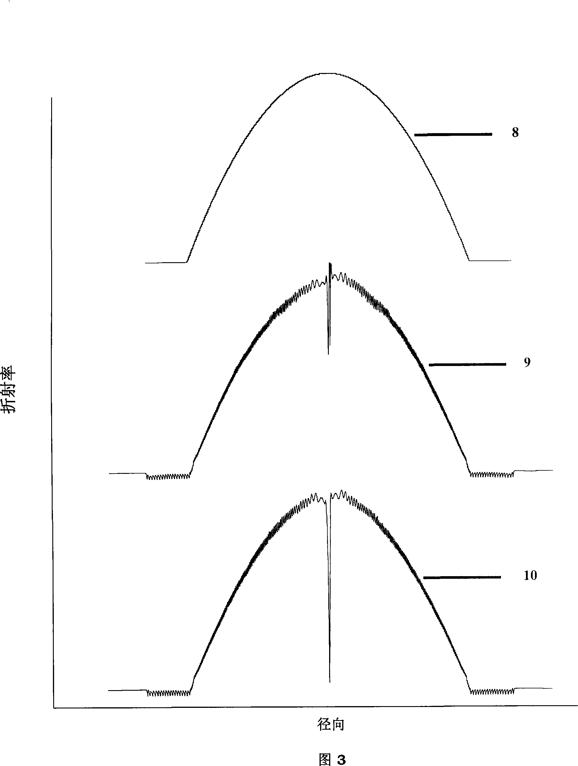
[0123] The preform is deposited according to conventional methods to achieve the target alpha value between 1.9 and 2 as described in the prior art, and the corresponding refractive index profile is measured by a profiler. The alpha value of this core layer was 1.96, which was close to the target value, but the core layer drawn from the mandrel had a very low bandwidth of 123 and 225 MHz·Km at wavelengths of 850 and 1300 nm, respectively.

example 2

[0125] The method according to the invention analyzes the above profile to determine the cause of the low bandwidth at target α. The dotted line of the layered delay diagram 16 of the mandrel above has great fluctuations with the ideal delay diagram 15, as shown in FIG. 6 . Based on this deviation from the ideal delay, correction factors for each layer are calculated using empirical equations. This correction factor is used to vary the dopant flux per layer to deposit a second core rod. The refractive index of this mandrel was measured to give an alpha value of 1.955. The profile was analyzed hierarchically according to the method of the present invention previously used to check for local variations. In Fig. 18, the time delay along the radial dotted line has been nearly reduced, as shown in Fig. 7. Comparing the time delay diagram 18 of the second mandrel with the time delay diagram 16 of Example 1, it is obvious that the difference between the ideal delay diagram and the...

example 3

[0127] Based on the correction factor obtained for the second mandrel, the layered dopant flux was further corrected to make another mandrel. The mandrel has an alpha value of 1.96, and a layered delay map is obtained from this example. This delay graph is very close to the ideal graph, except because of the center and edges of the central depression. After the core rod is stretched, its bandwidth is 750MHz·Km and 880MHz·Km at wavelengths of 850nm and 1300nm respectively.


PUM


Abstract

This invention relates to a novel protein, termed INSP152, herein identified as a secreted protein, in particular, as a MAM domain containing protein and to the use of this protein and nucleic acid sequence from the encoding gene in the diagnosis, prevention and treatment.

Description

technical field [0001] The present invention relates to a manufacturing method of multimode optical fiber with high bandwidth and multimode optical fiber, in particular to a method for manufacturing high bandwidth multimode optical fiber through the measurement technology of refractive index distribution. Background technique [0002] Fiber optic lightwave communication systems play an important role in voice and data transmission. Optical fibers used in communication systems may be single-mode optical fibers or multi-mode optical fibers. The present invention generally relates to methods of making multimode optical fibers. Nevertheless, the method disclosed in the present invention can also be used to manufacture single-mode optical fibers. [0003] A multimode fiber consists of a core that confines the entire signal and a cladding that surrounds the core. Typically, barrier layers are interposed between the core and cladding layers. Multimode optical fiber is drawn fro...

Claims


Application Information

Patent Timeline
IPC IPC(8): C03B37/025C03B37/07
CPCC03B37/0253G02B6/0288G02B6/03611G02B6/03622Y02P40/57
Inventor 潘纳哥・班加罗尔-克里希纳斯瓦米萨瓦・杜塔萨西斯・朗姆・潘内塞尔万森西尔・库马尔・纳格斯瓦兰
Owner STERLITE OPTICAL TECH
Why Eureka
Try Eureka