Self controlled high efficient gas and liquid separator

A gas-liquid separator and gas-liquid separation technology are applied in separation methods, dispersed particle separation, chemical instruments and methods, etc., and can solve the problems of high technical requirements for use and maintenance, high requirements for control systems, and complex control processes. Achieve the effect of low manufacturing and use cost, good separation effect and simple process

Inactive Publication Date: 2007-10-17
房师礼
View PDF0 Cites 16 Cited by
  • Summary
  • Abstract
  • Description
  • Claims
  • Application Information

AI Technical Summary

Problems solved by technology

This type of separator mainly has the disadvantages of large volume, complicated process, and high cost; the tubular cyclone separator uses the principle of centrifugal force to separate gas and liquid. Equipped with an accurate and reliable automatic control system, there are disadvantages such as complex control process, high cost, and high technical requirements for use and maintenance.

Method used


Image

  • Self controlled high efficient gas and liquid separator
  • Self controlled high efficient gas and liquid separator
  • Self controlled high efficient gas and liquid separator

Examples


Embodiment 1

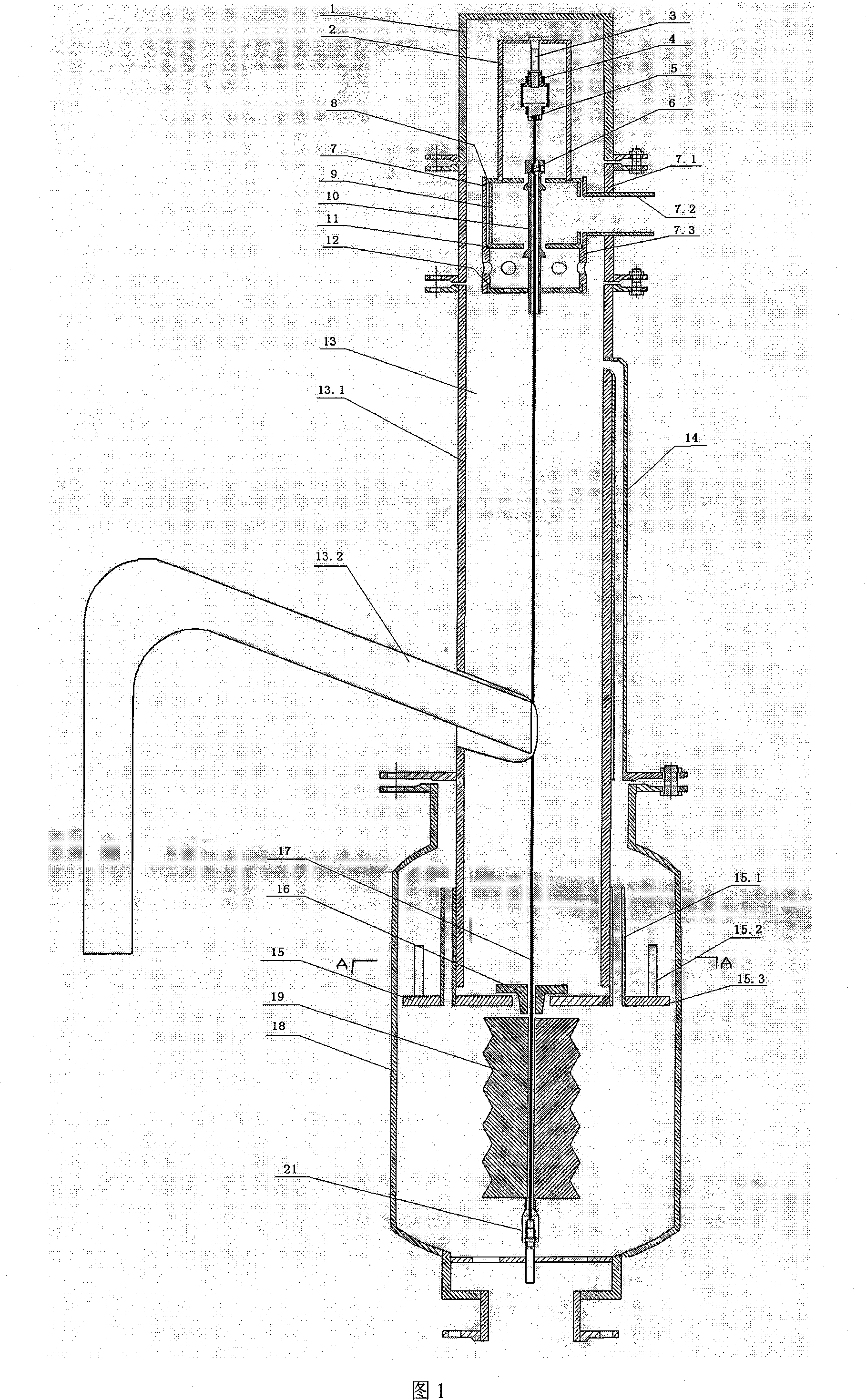
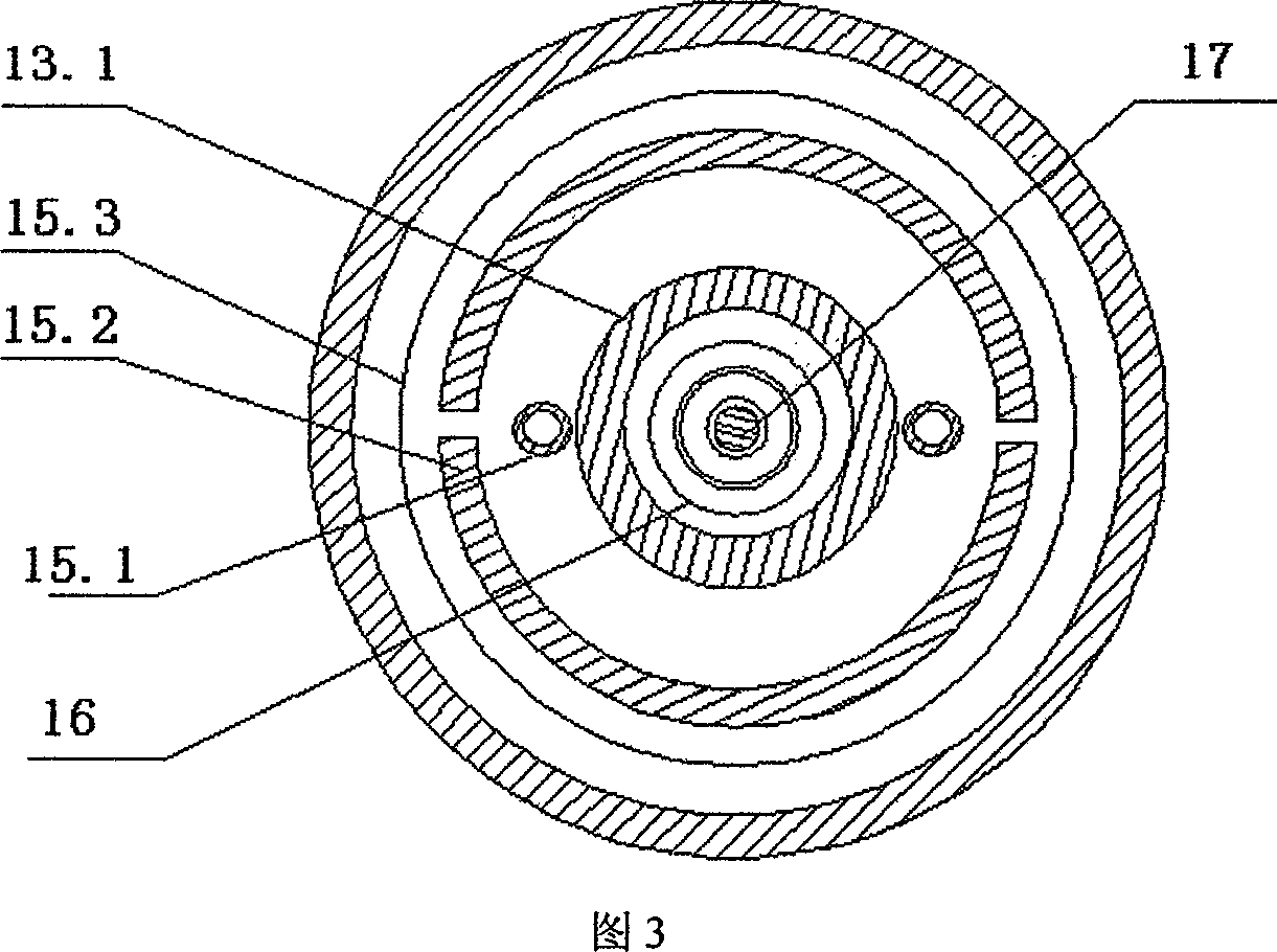
[0028] Embodiment 1: in conjunction with accompanying drawing 1 and 3, the present invention is described in further detail (gas-liquid mixed-phase medium can effectively separate gas phase through the scheme of above-mentioned automatic control high-efficiency gas-liquid separator):

[0029] Its technical scheme is: spring cover 1, bracket 2, adjustment rod 3, lock nut and washer 4, elastic element and connecting piece 5, air valve core fixing piece 6, air valve body 7, outer valve body 7.1, inner valve Body 7.2, outlet pipe 7.3, air valve seat 8, air valve positioning part 9, air valve core rod 10, air valve seat sealing ring 11, air valve centralizer 12, swirl separation unit 13, swirl separation body 13.1, air Liquid inlet pipe and nozzle 13.2, connecting pipe 14, auxiliary separation unit 15, 16, gas balance pipe 15.1, liquid level limit ring 15.2, disk 15.3, connecting rod 17, gravity separator 18, float 19.

[0030] The cyclone separation unit 13 is composed of a gas-li...

Embodiment 2

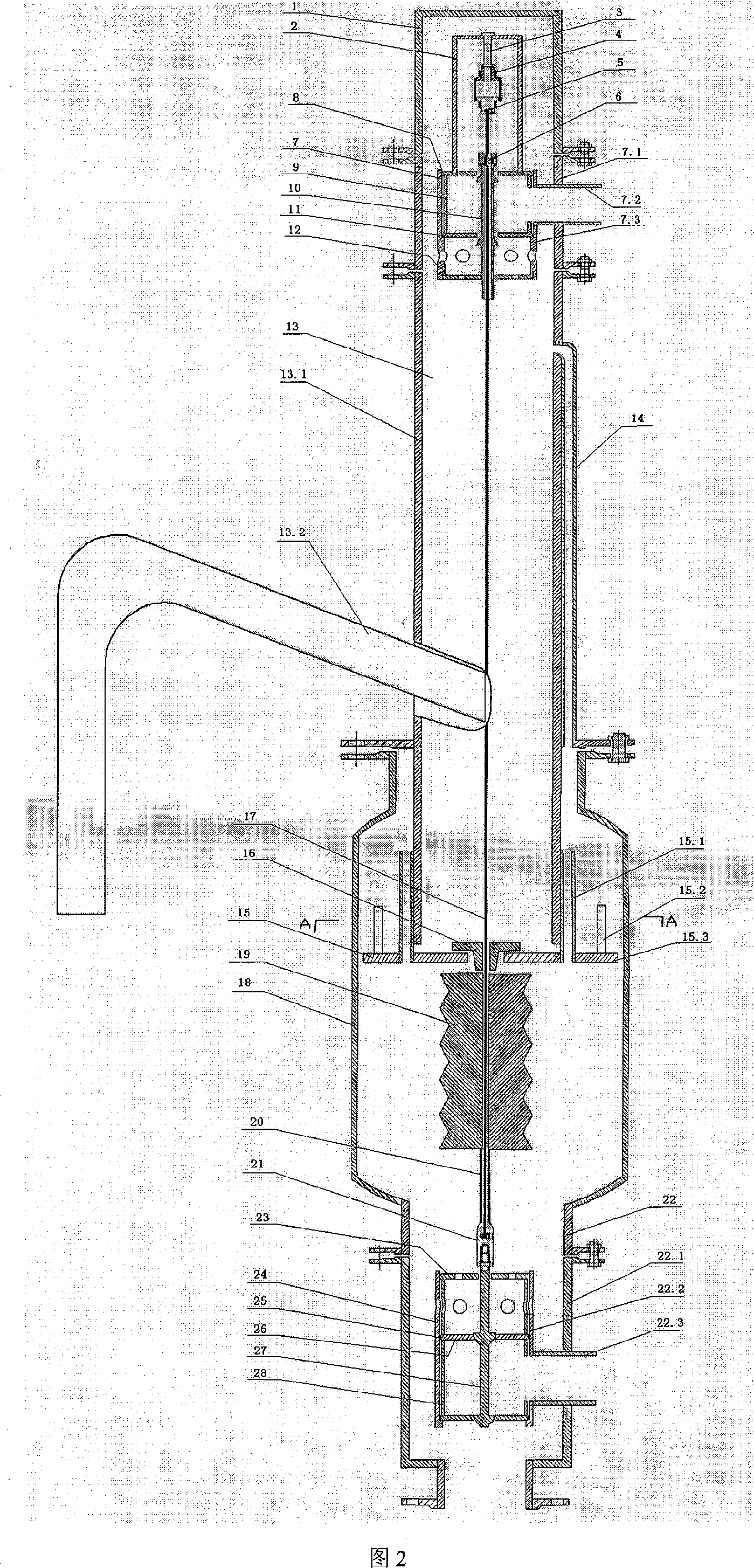
[0033] Embodiment 2: in conjunction with accompanying drawing 2 and 3, another kind of embodiment of the present invention is described in further detail (gas-liquid mixed-phase medium can effectively separate gas phase and liquid phase through the scheme of above-mentioned automatic control high-efficiency gas-liquid separator):

[0034] Its technical solution is: the above other structures remain unchanged, and the lower end of the gas-liquid separation unit can also be connected with a liquid adjustment unit. The outer valve body 22.1, the inner valve body 22.2, the liquid outlet pipe 22.3, the liquid valve centralizer 23, the liquid valve seat sealing ring 25, the liquid valve seat 26, the liquid valve core rod 27, and the liquid valve positioner 24,28 are formed.

[0035]The liquid valve body 22 is composed of a liquid valve outer valve body 22.1, an inner valve body 22.2, and a liquid outlet pipe 22.3. The upper end of the inner valve body 22.2 has an internal thread for ...


PUM


Abstract

The invention relates to a self-control gas-liquid separator, especially to a control and separation integral self-control high efficiency gas-liquid separator. The embodiment is to connect to the gas valve (7) of said gas conditioning unit through the lower end of the spring (1) in which a bracket (2) is mounted. The bracket (2) vertically hangs a liquid level transmitting control unit, and basipetally impenetrates the said gas conditioning unit and gas-liquid separating unit in turn. The beneficial effect is that: control-separate one-piece design of the self-control gas-liquid separator, whose control unit uses self-operated control principle and whose separating unit gives priority to hydrocyclone Separation process and assists with gravity separation, the efficiency for gas-liquid separating is high, and the effect of separation is excellent; the reasonable structure makes it easily to manufacturing activity and have a low manufacturing and using cost without maintenance and have a long longevity; compared with conventional gravity separator matching to the self-control system, the gas-liquid separating technological process is largely simplified and the cost can save larger than 70 percent at the same time.

Description

1. Technical field: [0001] The invention relates to a self-control gas-liquid separator, in particular to a control-separation integrated self-control high-efficiency gas-liquid separator. 2. Background technology: [0002] Gas-liquid separators are usually used for the separation of gas and liquid mixtures in the process of separate multi-phase metering and oil and gas gathering and transportation. At present, the commonly used gas-liquid separators mainly include vertical separators, horizontal separators, and tubular cyclone separators. No matter what kind of separator, it needs to be equipped with a corresponding control system to realize the normal separation of gas and liquid. The vertical separator and horizontal separator need a sufficiently large separator volume and stable separator liquid level to ensure a good gas-liquid separation effect. The supporting control methods mainly include float ball connecting rod control valve, gas ( Electric) dynamic automatic con...

Claims


Application Information

Patent Timeline
Patent Type & Authority Applications(China)
IPC IPC(8): B01D45/16B04C5/00B04C5/14F16T1/20
Inventor 朱桂林房师礼陈新民
Owner 房师礼
Why Eureka
Try Eureka