Electromagnetic fuel pump nozzle drive control method and its device

A control device, fuel pump technology, applied in the direction of fuel injection device, fuel injection control, electrical control, etc., can solve problems such as inability to correct or even give opposite predictions

Inactive Publication Date: 2007-10-17
塞尔福(厦门)工业有限公司
View PDF4 Cites 24 Cited by
  • Summary
  • Abstract
  • Description
  • Claims
  • Application Information

AI Technical Summary

Problems solved by technology

Theoretically, this method has a certain compensation effect on the fluctuation of power supply voltage and the change of coil

Method used


Image

  • Electromagnetic fuel pump nozzle drive control method and its device
  • Electromagnetic fuel pump nozzle drive control method and its device
  • Electromagnetic fuel pump nozzle drive control method and its device

Examples


Embodiment Construction

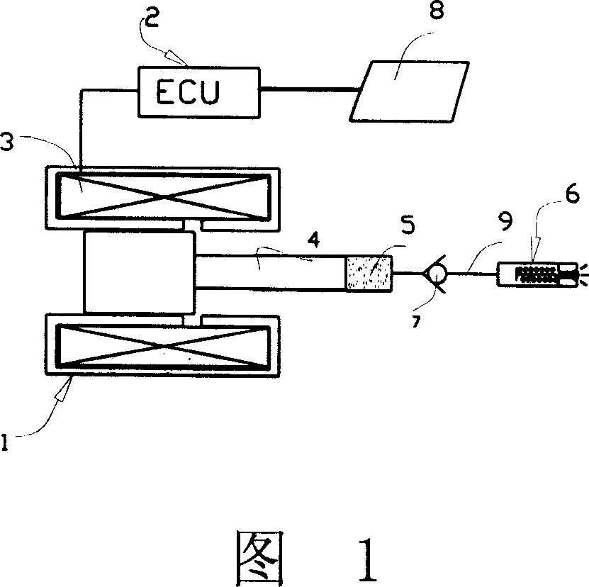
[0073] Figure 1 is a schematic diagram of the nozzle structure of an electromagnetic fuel pump. Its working process is: after the fuel enters the pressure delivery chamber 5, under the action of the plunger 4, it passes through the oil outlet valve 7 to the nozzle 6. When the fuel reaches a predetermined pressure, for example 15 bar, sprayed by nozzle 6. The movement of the plunger 4 comes from the electromagnetic force generated after the solenoid device 3 is energized, and the solenoid device 3 is driven by the PWM pulse voltage sent by the ECU unit 2 . The duty ratio of the PWM pulse voltage determines the fuel injection quantity Qi, and under the condition that other conditions remain unchanged, the fuel injection flow Qi is proportional to the driving pulse width T1. The demand of the engine for the fuel injection flow rate is mainly determined by the operating data 8 of the engine, which includes the engine speed, thermal load, and environmental conditions. This electro...


PUM


Abstract

A drive control method and drive control device for an electromagnetism fuel pump spray nozzle, an aiming feedback signal is obtained by a plunger displacement signal, especially characteristic parameters of the residual voltage curve, based on the aiming feedback signal a driving pulse width is predicted, the aiming oil quantity reached by each oil injection is controlled by the predicted driving pulse width, thereby realizing close loop control for the electromagnetism fuel oil pump nozzle device to improve precision supplied for the engine fuel, and avoid and reduce change of jet flow caused by factors such as mechanical wear, change of backspring force, change of nozzle opening pressure, change of fuel channel resistance, change of nozzle flow coefficient, change of friction force brought by the change of liquid viscidity and fuel impurity, change of driving voltage, in the meanwhile, the invention can realize real time monitoring for the working of the electromagnetism fuel injection pump nozzle by the ECU unit, and perform abnormal condition and fault diagnosis.

Description

technical field [0001] The invention belongs to the technical field of engines, and in particular relates to an engine management system, in particular to a closed-loop control method and device for an electromagnetic fuel pump nozzle device. Background technique [0002] Electromagnetic fuel pump nozzles, as a new type of fuel supply unit, have been proven to be applied to engine management systems, especially in two-wheeled motor vehicles powered by single-cylinder engines. The specific structure of this type of electromagnetic fuel pump nozzle device is described in Chinese patent ZL01103954.X "Electric Fuel Injection Device", Chinese Patent Application 200510119712.6 "A Fuel Injection Device", and patent application CN1474910A "Electronic Control Fuel Injection Device" . The electromagnetic fuel pump nozzle includes an electromagnetic pump and a nozzle, the electromagnetic pump includes a solenoid, a plunger and a fuel pressure delivery chamber, ...

Claims


Application Information

Patent Timeline
IPC IPC(8): F02D41/32F02M51/04F02M57/02F02M69/00
Inventor 郗大光杨延相刘昌文
Owner 塞尔福(厦门)工业有限公司
Why Eureka
Try Eureka