Electric-powered air release valve and blood pressure gauge

一种排气阀、电动的技术,应用在血压计领域,能够解决影响测量精度、可动部分重、排气特性变化等问题,达到高精度血压测量、改善控制特性、组装作业容易的效果

Active Publication Date: 2007-10-17
NIPPON SEIMITSU SOKKI KK
View PDF2 Cites 4 Cited by
  • Summary
  • Abstract
  • Description
  • Claims
  • Application Information

AI Technical Summary

Problems solved by technology

[0014] Therefore, not only is it difficult to achieve a compact structure, but also requires precise assembly work, which increases production costs
[0015] Also, since the moving parts become heavy, for example, for wrist-type sphygmomanometers, different postures when measuring blood pressure can cause changes in the exhaust characteristics, thereby affecting measurement accuracy
[0016] In addition, in the past, the movable coil electric exhaust valve, which was powered by cutting the magnetic field of the permanent magnet transversely with the coil current, mainly adjusted the opening degree of the valve by generating a force proportional to the coil current. Proportional decompression control, but in fact, when squeezing the uneven surface of the rubber valve (the rubber valve is provided with unevenness on the pressing surface of the rubber valve) for slow exhaust, the initial force of extrusion is weak , but each time you increase the extrusion amount, you need to squeeze with a stronger force. Therefore, it is difficult to perform control proportional to the coil supply current, and it is necessary to perform more troublesome control.

Method used


Image

  • Electric-powered air release valve and blood pressure gauge
  • Electric-powered air release valve and blood pressure gauge
  • Electric-powered air release valve and blood pressure gauge

Examples


Embodiment Construction

[0059] Hereinafter, various embodiments of the present invention will be described in detail with reference to the drawings.

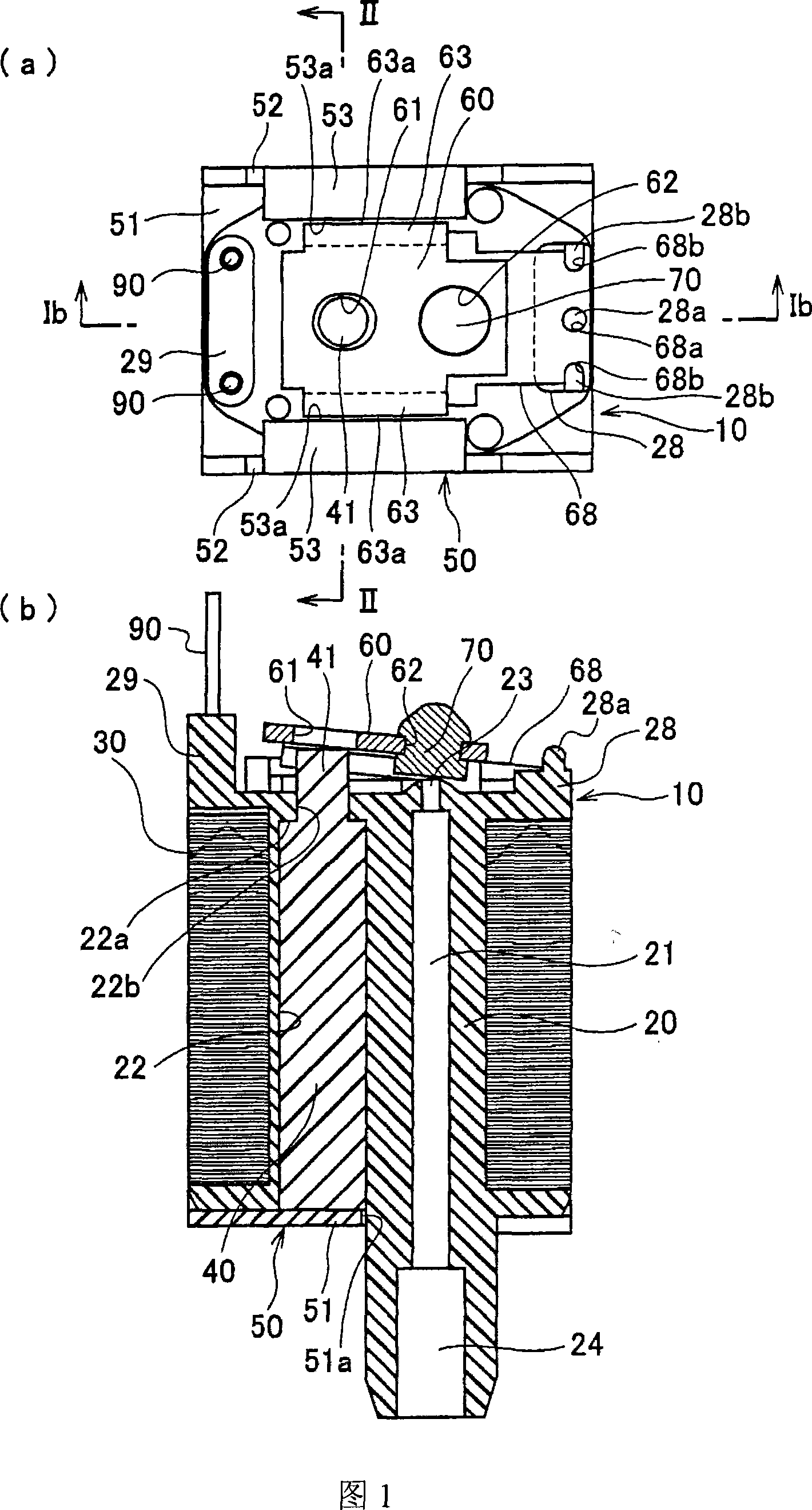
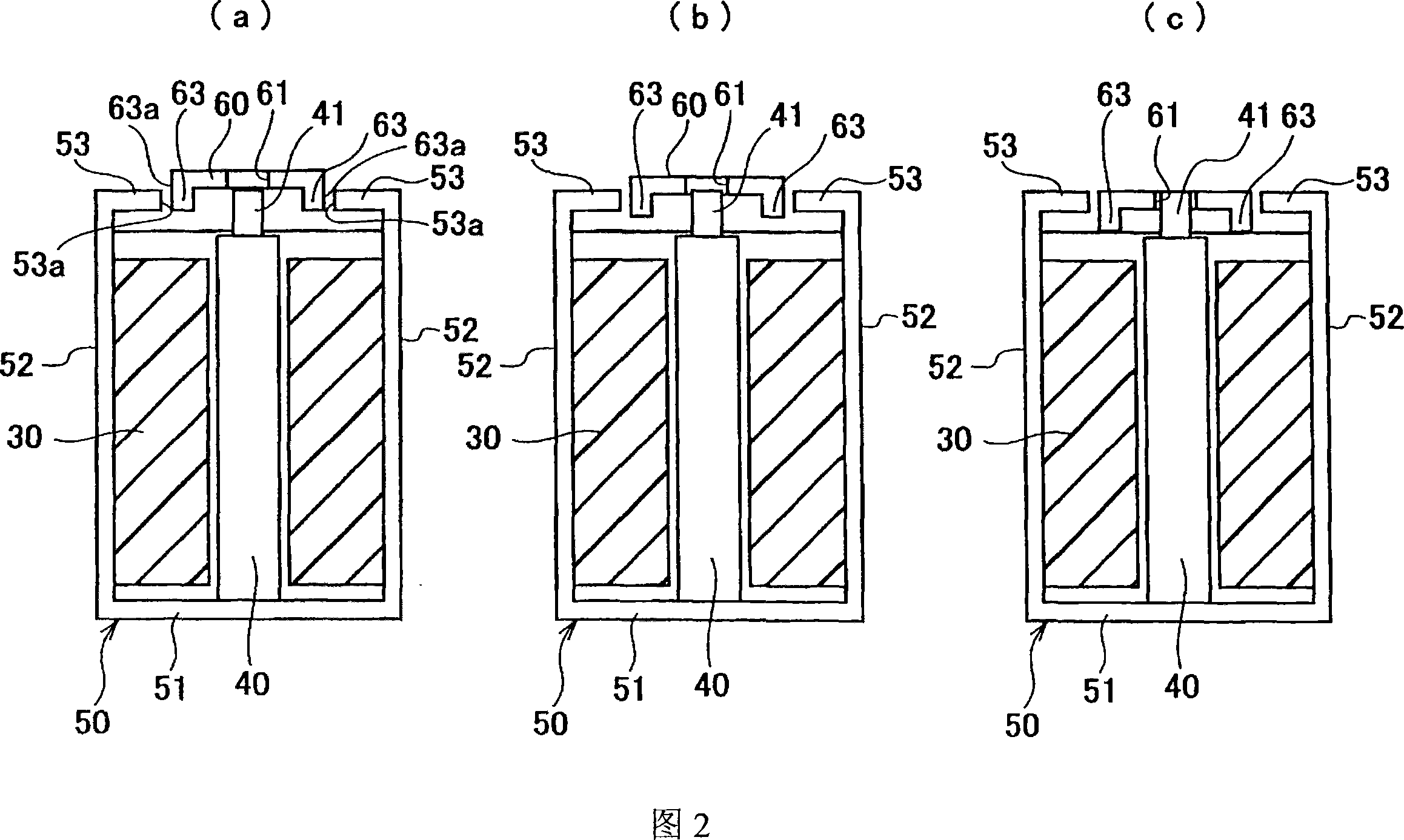
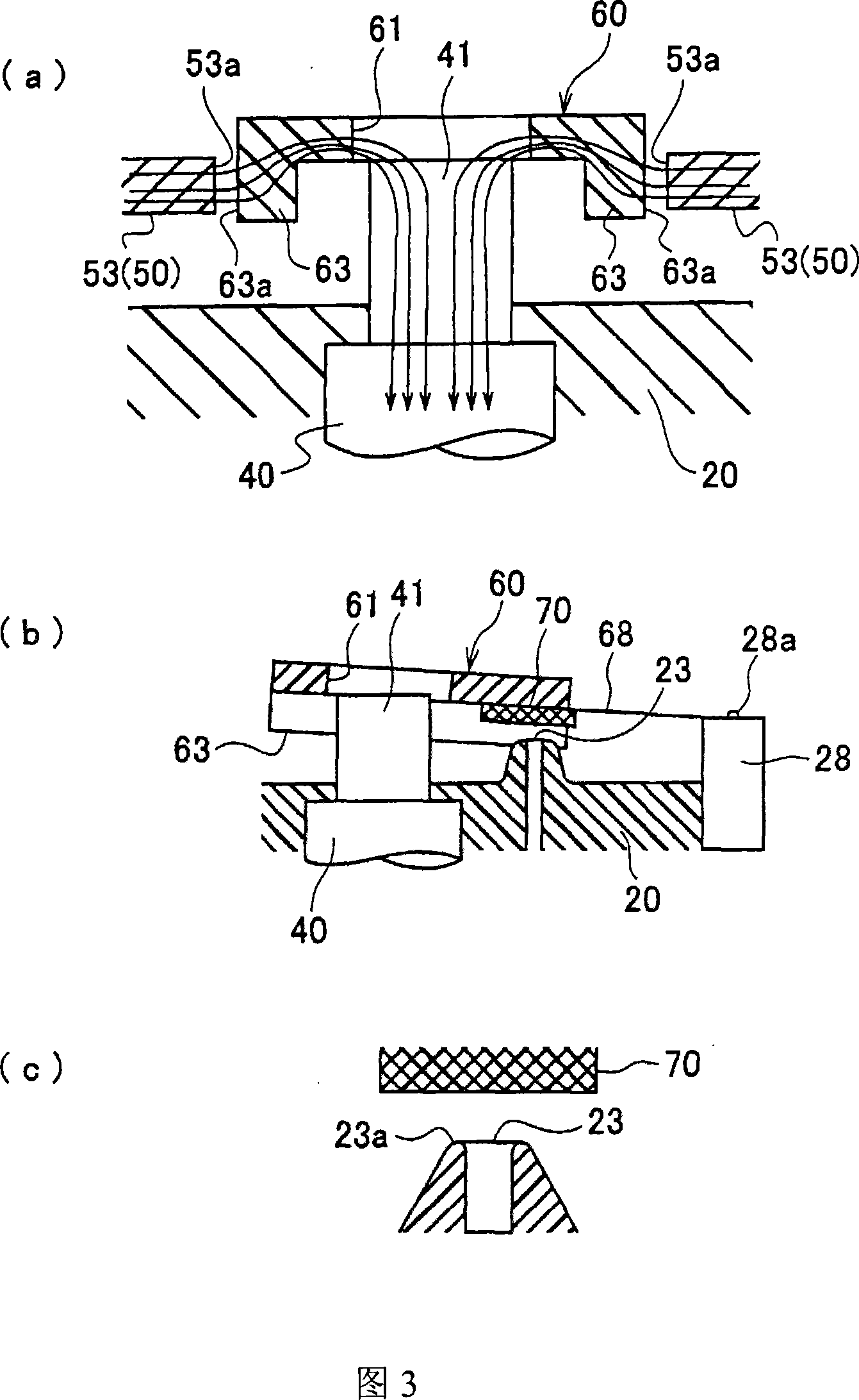
[0060] Fig. 1 is the structural representation of the electric exhaust valve 10 that the present invention relates to, (a) is a plan view; (b) is along (a) middle Ib—the sectional view that the direction shown by Ib arrow cuts off. Fig. 2 is a simplified sectional view taken along the direction indicated by II——II arrow in Fig. 1(a), (a) is a schematic diagram of the state before applying the driving force or the initial state of applying the driving force; (b) is applying a medium driving force A schematic diagram of the state; (c) is a schematic diagram of the state when the maximum driving force is applied. In addition, Fig. 3, Fig. 4 and Fig. 5 are simplified enlarged schematic diagrams of the states shown in Fig. 2 (a), (b) and (c) respectively, wherein (a) is the main part and the magnetic flux in Fig. 2 after enlargement A schematic diagram of ...


PUM


Abstract

The present invention provides an electric exhaust valve of simple and compact structure easily assembled to reduce production cost and exhibiting stable characteristics regardless of the posture difference. The electric exhaust valve has a nozzle 23 provided at the end of an air passage 21 in a bobbin 20; a fixed iron core 40 disposed in the bobbin side by side with the nozzle; an exciting coil 30 magnetizing the fixed iron core by carrying a current; a movable iron piece 60 displaced toward the nozzle from its initial position according to the magnetic attracting force when the fixed iron core is magnetized; a plate spring 68 energizing the movable iron piece into the initial position; a rubber valve 70 provided at the movable iron piece to adjust the opening of the nozzle; and a yoke 50 with its tip parts facing both side parts of the movable iron piece through magnetic gaps. The movable iron piece is formed with a circular hole 61 into which one end cylindrical part 41 of the fixed iron core can intrude when the movable iron piece is displaced toward the nozzle, and a magnetic gap is secured between the inner periphery of the circular hole and the outer periphery of the one end cylindrical part.

Description

technical field [0001] The invention relates to an electric exhaust valve suitable for an exhaust device of a sphygmomanometer and a sphygmomanometer using the electric exhaust valve. Background technique [0002] Generally speaking, a sphygmomanometer increases the pressure in the cuff to a certain value, decompresses it slowly, and measures the blood pressure during the decompression process. This sphygmomanometer uses an electric exhaust valve to slowly reduce the pressure in the cuff. [0003] For a conventional example of an electric exhaust valve used in a sphygmomanometer, reference may be made to the content described in Patent Document 1. This electric exhaust valve belongs to the movable coil type, and its structure is shown in Figure 7. [0004] In FIG. 7, 201 is a main body case, and 202 is a front-end case. An air channel 203 communicating with the pump and the cuff is provided on the front end housing 202 that closes the front end opening of the body housing...

Claims


Application Information

Patent Timeline
Patent Type & Authority Applications(China)
IPC IPC(8): F16K1/00F16K31/06A61B5/022
CPCH01F7/14F16K31/0682A61B5/022F16K31/10
Inventor 高桥幸雄
Owner NIPPON SEIMITSU SOKKI KK
Why Eureka
Try Eureka