
A reservoir pre-discharge and ecological flow discharge structure

An ecological flow and reservoir technology, applied in water conservancy projects, sea area projects, construction, etc., to achieve the effect of cost economy, simple building structure, and saving engineering investment

Active Publication Date: 2018-11-09
POWERCHINA ZHONGNAN ENG
View PDF6 Cites 1 Cited by
  • Summary
  • Abstract
  • Description
  • Claims
  • Application Information

AI Technical Summary

Problems solved by technology

Due to the construction of the reservoir dam, it forms a barrier to the natural river, and it is generally necessary to set up a separate ecological flow discharge facility to meet the daily discharge requirements of the downstream ecological flow, which further increases the project investment.

Method used


Image

  • A reservoir pre-discharge and ecological flow discharge structure
  • A reservoir pre-discharge and ecological flow discharge structure

Examples


Embodiment Construction

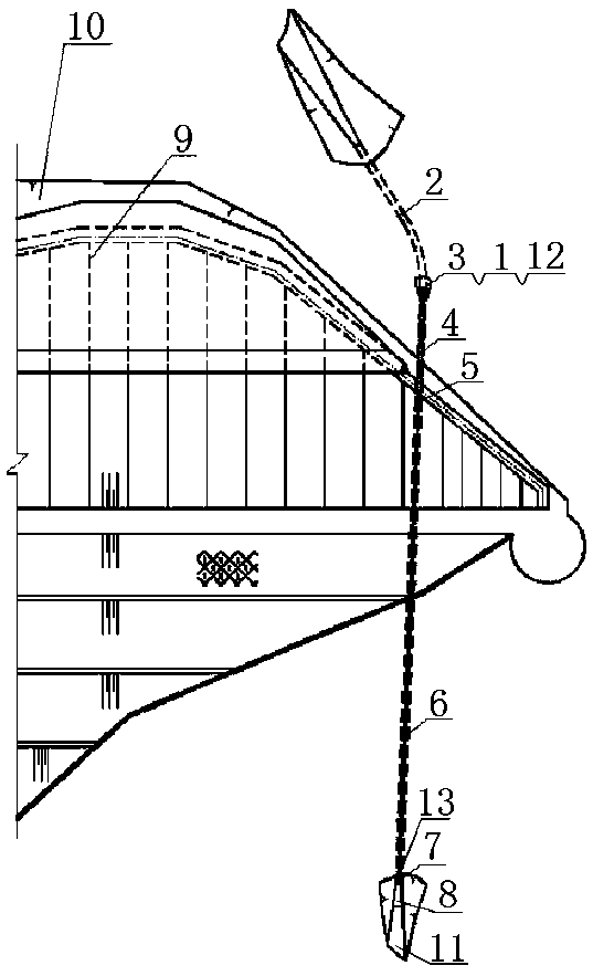
[0025] like Figure 1 to Figure 2 As shown, an embodiment of the present invention includes a diversion tunnel 2, a connecting pipe 6 and a vertically arranged vertical shaft 3, and the vertical shaft 3 is arranged at a suitable position in the front section of the diversion tunnel 2 according to the terrain, and the vertical shaft 3 connects the reservoir 10 with the The diversion hole 2 is connected, and the connecting pipe 6 fits the inner wall of the shaft 3 and extends to the outlet 13 of the diversion hole. A stilling pool 8 is provided at the outlet of the connecting pipe 6, and the stilling pool 8 is used to dissipate energy and prevent scour of the discharged water flow, and guide the discharged water flow to the downstream outlet 11 after energy dissipation. The connecting pipe 6 in the diversion tunnel 2 is provided with a plugging body 4 outside. The plugging body 4 is arranged at a suitable position in the diversion tunnel 2. The length of the arrangement slightly...


PUM


Abstract

The invention discloses a structure integrating reservoir pre-discharging and ecological flow discharging. The structure comprises a flow guide hole, a communicating pipe and a vertical shaft which is vertically arranged. The reservoir communicates with the flow guide hole through the vertical shaft. The communicating pipe is attached to the inner wall of the vertical shaft and extends to an outlet of the flow guide hole. The elevation of an inlet of the communicating pipe is lower than a normal water storage level of the reservoir and is higher than a dead water level of the reservoir. A stilling pool is arranged at an outlet of the communicating pipe. A blocking body is arranged at the outer portion of the part, in the flow guide hole, of the communicating pipe. A first valve controlling the communicating pipe to be opened and closed is arranged at the tail end of the blocking body. A second valve used for adjusting the flow of the communicating pipe is arranged at the tail end of the communicating pipe. By means of the structure integrating reservoir pre-discharging and ecological flow discharging, floods needing pre-discharging in the reservoir or ecological flow are discharged to the downstream part in time and in order. Compared with a common pre-discharging facility bottom hole discharging hole, the structure integrating reservoir pre-discharging and ecological flow discharging is simple in construction structure, economical in construction cost and convenient to maintain, good technical economy popularization value is achieved on a project which is small in rain collecting area and needs to be provided with a pre-discharging facility, and the structure is suitable for the reservoir high in reservoir slit elevation.

Description

technical field [0001] The invention belongs to the technical field of hydropower and water conservancy engineering construction, and in particular relates to a reservoir pre-discharge and ecological flow discharge structure. Background technique [0002] The lower reservoir of the pumped storage power station is low-lying and has a lot of natural inflow or runoff, so it is generally necessary to set up drainage structures. When the rainwater collection area of ​​the reservoir is small but the consequences of engineering accidents are serious, in order to ensure the safe operation of the reservoir and from the technical and economic point of view, open spillways without gates are generally still installed as emergency flood discharge facilities. Since the open spillway without gates can only discharge floods higher than the normal water storage level, and the power generation flow of the upper reservoir and the natural inflow flood of the lower reservoir are superimposed dur...

Claims


Application Information

Patent Timeline
Patent Type & Authority Patents(China)
IPC IPC(8): E02B8/06
CPCE02B8/06
Inventor 刘纯冯树荣熊文清石含鑫李华艳胡育林宁永升窦灿
Owner POWERCHINA ZHONGNAN ENG
Learn More