Swirl high energy magnetic coupling switch
A magnetic coupling and magnetic coupler technology, applied in the direction of permanent magnet clutches/brakes, electromechanical devices, electrical components, etc., can solve the problem of reduced reliability and service life of switches, poor electrode discharge and heat dissipation performance, and bulky switch structures, etc. problems, to achieve the best arc extinguishing effect, long service life, and improve the effect of heat dissipation conditions
Active Publication Date: 2010-12-01
牡丹江旋宇激光有限公司
View PDF3 Cites 0 Cited by
- Summary
- Abstract
- Description
- Claims
- Application Information
AI Technical Summary
Problems solved by technology
At present, in high-voltage pulse and high-current discharge devices, most of them use electric spark pre-disconnection switches. These switches generally have poor electrode discharge and heat dissipation performance, which leads to electrode ablation and sputter contamination, which makes the reliability of the switch and reduced service life
Most of the rotary switches use a special gas system to blow away the electrode sputtering, which makes the whole switch structure bulky.
Method used
View moreImage
Smart ImageViewing Examples
Examples
Embodiment Construction
Login to View More PUM
 Abstract
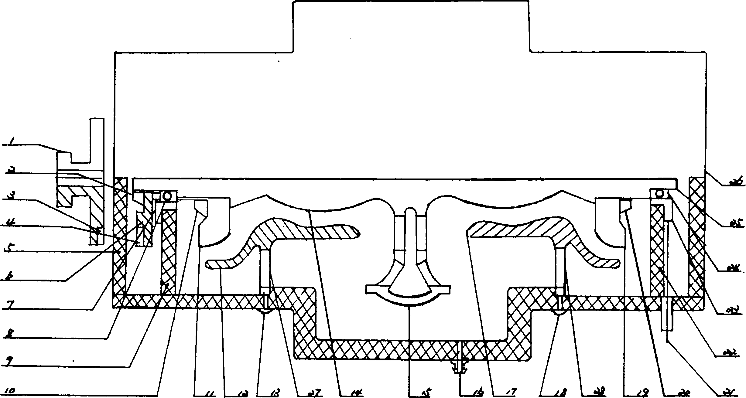
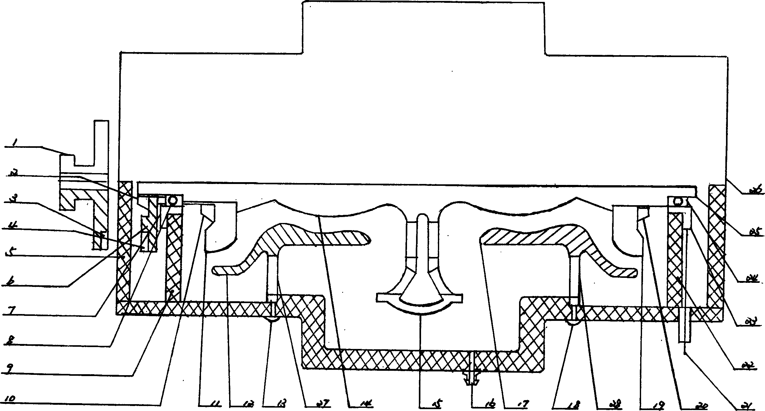
A vortex high-energy magnetic coupling switch, wherein the rotation of coupling discs (1) (6), drive the rotation of leaves (11) (19) on a circular trigger electrode axis (25) to produce a high-speed vortex field. The high-speed rotary vortex field takes away the ionized gas sputtering substance generated by the discharge of an electrode (14) and electrodes (12) (17), through a collection purifier (15), cycling from area B to area A through airflow windows (27) (28), thus improving the electrode cooling conditions to prevent electrode ablation from polluting the electrode cavity, and extending the service life. The invention applies to all kinds of high voltage, high current, and anti-impact pulse discharging devices.
Description
Eddy current high energy magnetic coupling switch technical field The invention adopts the eddy current wrapping technology, belongs to the spark discharge device, and is an eddy current high-energy magnetic coupling switch. Background technique At present, in high-voltage pulse and high-current discharge devices, most of them use electric spark pre-disconnection switches. These switches generally have poor electrode discharge and heat dissipation performance, which leads to electrode ablation and sputter contamination, which makes the reliability of the switch and reduced service life. Most of the rotary switches use a special gas system to blow away the electrode sputtering, which makes the whole switch structure heavy. The purpose of the present invention is to solve the "bottleneck" problem of high-energy and fast discharge, and provide a high-voltage, high-current, and shock-resistant high-energy battery that works reliably, does not easily ablate electrodes, does n...
Claims
Login to View More Application Information
Patent Timeline
 Patent Type & Authority Patents(China)
IPC IPC(8): H02K51/00H02K49/10H01T7/00
Inventor 程鹏
Owner 牡丹江旋宇激光有限公司
Features
- R&D
- Intellectual Property
- Life Sciences
- Materials
- Tech Scout
- Unparalleled Data Quality
- Higher Quality Content
- 60% Fewer Hallucinations
Learn More Browse by: Latest US Patents, China's latest patents, Technical Efficacy Thesaurus, Application Domain, Technology Topic, Popular Technical Reports.
© 2025 PatSnap. All rights reserved.Legal|Privacy policy|Modern Slavery Act Transparency Statement|Sitemap|About US| Contact US: help@patsnap.com


