Plate type cold trap for freeze-dryer

A technology for freeze dryers and cold traps, which is applied in the field of plate cold traps for freeze dryers, and can solve the problem that the power per unit surface area is small and is not suitable for large freeze dryers, the heat exchange area is not fully utilized, and the tube cold trap occupies Large space and other problems, to achieve the effect of shortening the pre-evacuation time, shortening the defrosting time, and reducing equipment investment

Active Publication Date: 2007-10-24
联合冻干有限公司
View PDF0 Cites 1 Cited by
  • Summary
  • Abstract
  • Description
  • Claims
  • Application Information

AI Technical Summary

Problems solved by technology

[0003] The cold traps (built-in type and external built-in type) of the existing freeze dryers mostly adopt the tube structure of copper tube, galvanized steel tube or stainless steel tube, which are divided into coil type (spiral tube, serpentine tube) and column tube type. Due to the limitation of the tube structure and layout, the tube type cold trap not only occupies a large space, but also has a long process flow and large flow resistance, which is not conducive to the evaporation of the working fluid or the heat exchange of the refrigerant, and there are a large number of uneven surface temperatures. On the leeward side, the effective heat exchange area is not fully utilized, the flow resistance of water vapor is large, and ice blockage is easy to occur on the windward side, so the water capture efficiency of the tubular cold trap is very low and the energy consumption is also large
[0004] There is a plate type cold trap on the small freeze dryer, which is formed by embedding a coil in a flat material (mostly aluminum), which is actually a modified tube type cold trap, which also has some shortcomings of the tube type cold trap , due to the small power per unit surface area, it is not suitable for large freeze dryers

Method used


Image

  • Plate type cold trap for freeze-dryer
  • Plate type cold trap for freeze-dryer
  • Plate type cold trap for freeze-dryer

Examples


Embodiment Construction

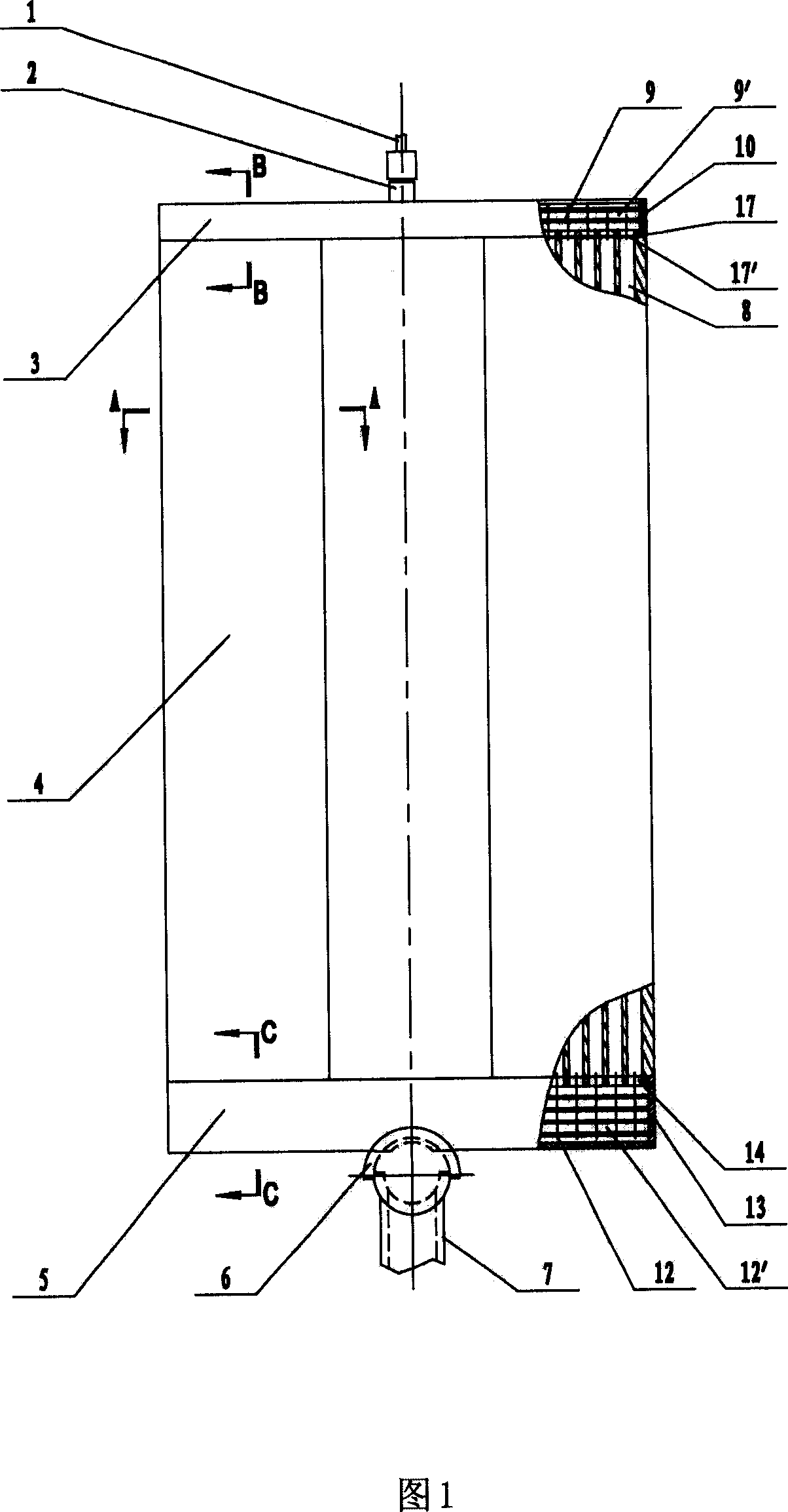
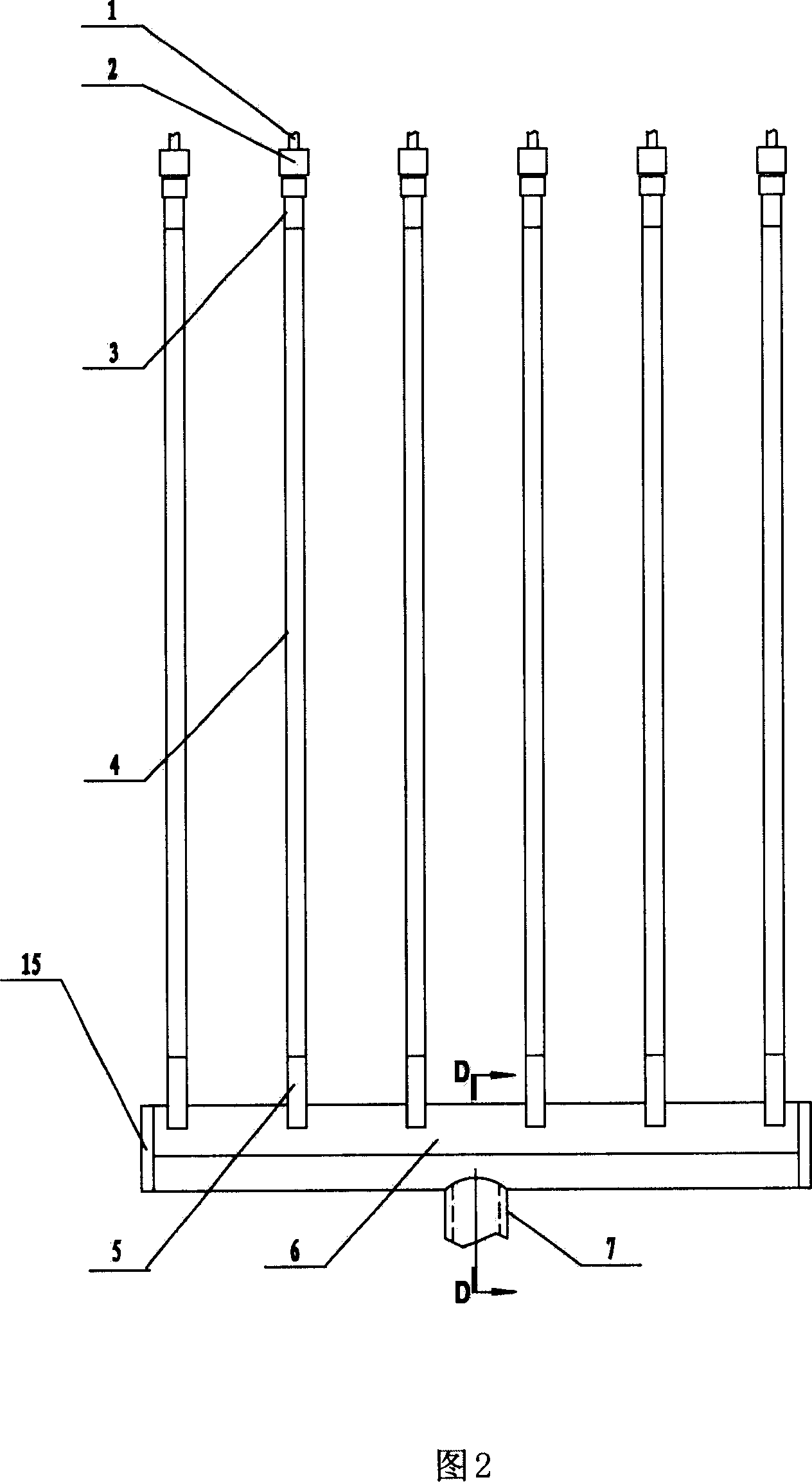
[0024] As Fig. 1, 2 is the schematic diagram of plate type cold trap used in this freeze dryer, has shown the plate type cold trap used in freeze dryer among the figure, and it comprises liquid pipe 1, liquid joint 2, liquid separation small header 3, cold Well main board 4, throttling plate 17, return air small header 5, return air cross header 6 and return air main pipe 7; several cold trap main boards 4 are arranged in parallel and equidistant or fan-shaped arrangement, and this scheme is parallel and equidistant Arrangement, the upper end of each said cold trap main board 4 is equipped with a throttling plate 17 and is connected with the described liquid separation small header 3; each said liquid separation small header 3 is equipped with said The liquid tap 2; the other end of the liquid tap 2 is connected to the liquid pipe 1; the lower end of each cold trap main board 4 is equipped with the small air return header 5; The lower end of each described air return small hea...


PUM


Abstract

Plate cold trap is used for freeze-drying machine, its characteristics are: it includes the fluid-dividing pipe (1), fluid-dividing adaptor (2), fluid-dividing small head (3), cold trap main plate (4), choke plate (17), return-air small head (5), return-air horizontal header (6) and return-air main pipes (7); several cold trap main plates (4) are parallel-ranged in equal distance or are ranged in fan shape, upper end of each cold trap main plates (4) is equipped with fluid-dividing small header (3); each fluid-dividing small header (3) is equipped with fluid-dividing adaptor (2); another end of fluid-dividing adaptor (2) is connected with fluid-dividing pipe (1); lower end of each cold trap main plates (4) is equipped with return-air small head (5); lower end of each return-air small head (5) is installed on the return-air horizontal header (6) and the return-air main pipes (7) is also installed on the return-air horizontal header (6). The invention has small size, low power consumption, high water-catching efficiency and low manufacture costs, it is easy to defrost and can realizes the straight-expansion fluid-supply of freeze-drying cold trap.

Description

technical field [0001] The invention relates to a vacuum freeze dryer (hereinafter referred to as a freeze dryer), in particular to a plate cold trap for a freeze dryer. Background technique [0002] Freeze-drying technology is to freeze the water-containing material to the temperature below the eutectic point, so that the water in it becomes ice, and then sublimates the ice into water vapor to escape from the material at an appropriate temperature and vacuum, and uses a cold trap to freeze the Water vapor desublimation, so as to obtain the technology of drying products. When the freeze dryer is working, the vacuum in the freeze-drying chamber is obtained by the vacuum system, which is mainly composed of a vacuum unit and a cold trap. During the drying process, a large amount of sublimated water vapor cannot be completely discharged out of the warehouse by the vacuum unit alone. The vacuum machine is only used to extract non-condensable gas. For the water vapor in the gas, ...

Claims


Application Information

Patent Timeline
Patent Type & Authority Applications(China)
IPC IPC(8): F26B5/06F28D1/02
Inventor 王一田王佳文徐春强熊恩国
Owner 联合冻干有限公司
Why Eureka
Try Eureka