
Chirp impulse compression method and device

A technology of chirped pulse and compression method, which can be used in laser parts, optics, instruments, etc., and can solve problems such as limiting laser pulses

Inactive Publication Date: 2007-10-24
INST OF PHYSICS - CHINESE ACAD OF SCI
View PDF0 Cites 14 Cited by
  • Summary
  • Abstract
  • Description
  • Claims
  • Application Information

AI Technical Summary

Problems solved by technology

[0007] However, the disadvantage of chirped mirrors in the prior art is that their damage threshold is only a few Joules / cm 2 order of magnitude, limiting the generation of higher power laser pulses

Method used


Image

  • Chirp impulse compression method and device
  • Chirp impulse compression method and device
  • Chirp impulse compression method and device

Examples


Embodiment Construction

[0035] The present invention will be further described in detail below in conjunction with the drawings and specific embodiments:

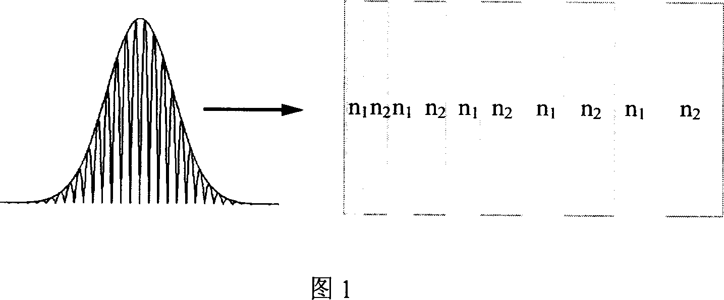
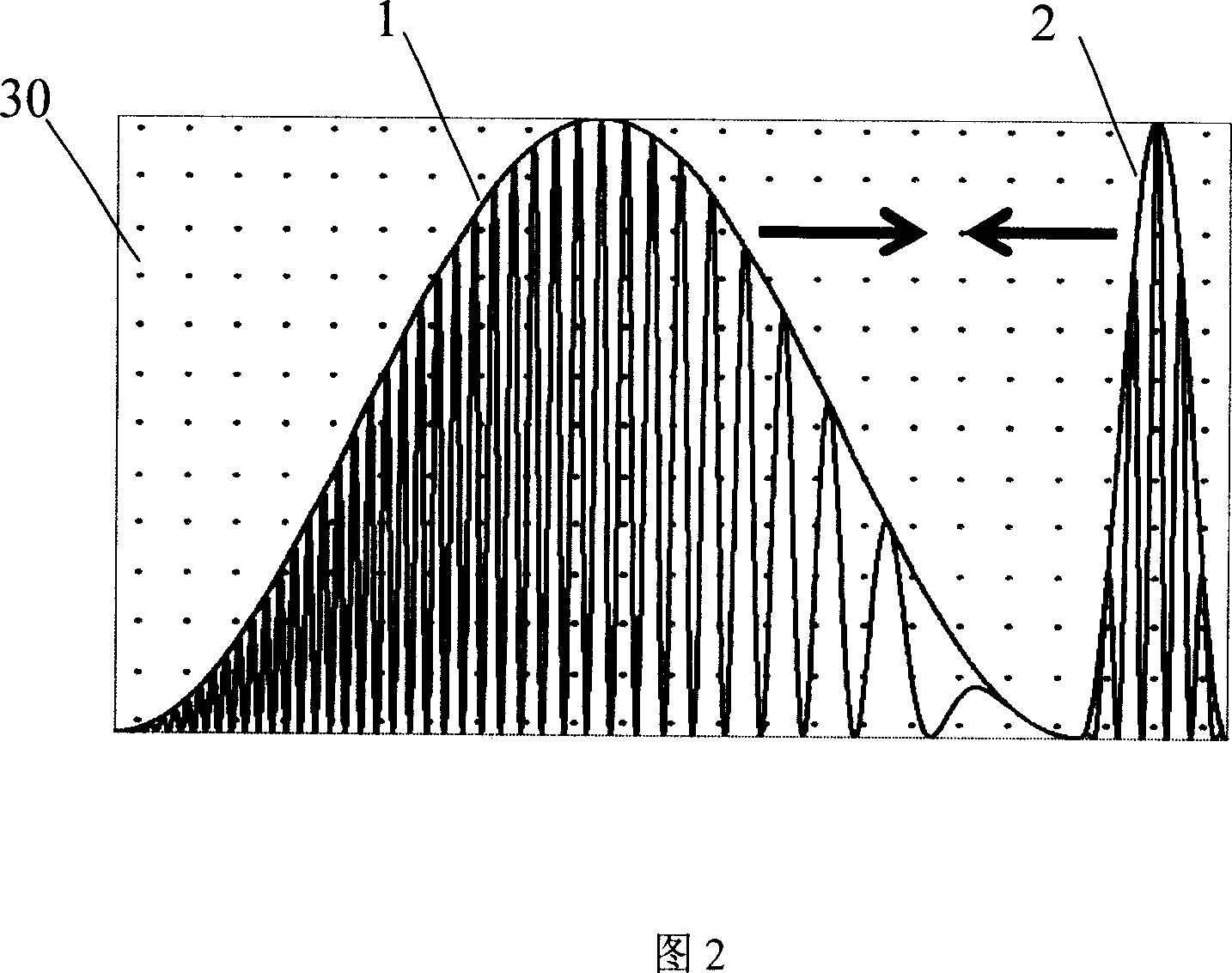
[0036] Plasma is a state of matter composed of free electrons and ions after general matter is ionized. The plasma is electrically neutral as a whole. Since plasma has no thermal damage threshold, it is a special medium capable of controlling intense laser pulses. The present invention is a chirped pulse compression method and device based on plasma medium.

[0037] Plasma, a gaseous substance, cannot be processed into thin layers of different thicknesses like ordinary transparent media, and then bonded together. The present invention uses optical methods to produce plasma chirped pulse compression device

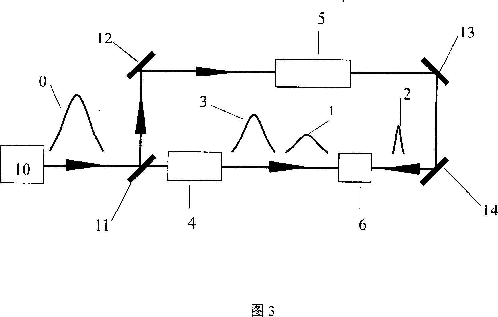
[0038] 3, the production of a chirped pulse compression device of the present invention includes: a laser 10 emits a laser chirped pulse 0, the laser 10 is a titanium-doped sapphire laser, the laser wavelength is 0.8 microns, and the laser pulse wi...


PUM


Abstract

The invention discloses a chirp pulse compression method and a relative device, based on plasma, wherein the method comprises that (1), providing a section of plasma, (2), providing a first chirp pulse incident into the plasma, (3), providing a second chirp pulse incident into the plasma, (4), emitting the object chirp laser pulse along the direction same as the first chirp pulse into the plasma. And the device comprises a laser for emitting a laser chirp pulse, a light splitter for splitting the laser chirp pulse into two beams, while one beam via a split delay device is divided into a first chirp pulse an a third chirp pulse, and another beam via a pulse compressor forms a second non-chirp pulse, the first and the second chirp pulses are emitted to a plasma generated by a plasma generator, the second non-chirp pulse is reversed emitted into the plasma. The invention has high pulse compression efficiency and high light intensity damage threshold value.

Description

Technical field [0001] The invention relates to a pulse compression method and device, in particular to a chirped pulse compression method and device using plasma. Background technique [0002] Since the first laser was invented in the 1960s, lasers are not only a powerful scientific research tool for understanding the nature of nature, but also affect people's work and life in various fields, such as medical treatment and micro-processing. With the development and diversification of the laser itself, its utilization value will be more fully utilized. [0003] High-power laser technology is the most important development direction in the laser field. The most important driving force for the development of powerful lasers is laser nuclear fusion, which uses the radiation generated by multiple lasers to compress a deuterium-tritium target pellet to achieve a nuclear reaction. Laser nuclear fusion is expected to provide humans with inexhaustible energy. Countries all over the world,...

Claims


Application Information

Patent Timeline
IPC IPC(8): G02F1/39G02F1/35H01S3/00
Inventor 武慧春盛政明张杰
Owner INST OF PHYSICS - CHINESE ACAD OF SCI
Learn More