Fluid ejecting device and method for making the same

A technology of fluid injection and production methods, which is applied in printing and other directions, can solve the problems of not effectively improving the heat utilization rate, increasing the power of the injection device, accelerating the dissipation of heat energy, etc., and achieving a significant effect of heat insulation

Inactive Publication Date: 2007-10-31
BENQ CORP
View PDF1 Cites 3 Cited by
  • Summary
  • Abstract
  • Description
  • Claims
  • Application Information

AI Technical Summary

Problems solved by technology

However, accelerating the dissipation of heat energy cannot effectively increase...

Method used


Image

  • Fluid ejecting device and method for making the same
  • Fluid ejecting device and method for making the same
  • Fluid ejecting device and method for making the same

Examples


Embodiment Construction

[0039] Hereinafter, the present invention will be described in detail with examples and accompanying drawings. In the drawings or descriptions, similar or identical parts use the same symbols. In the drawings, the shape or thickness of the embodiments may be exaggerated to simplify or facilitate labeling. Part of the elements in the drawings will be described in the description. It is to be understood that elements not shown or described may have various forms known to those skilled in the art. Furthermore, when it is stated that a layer is on a substrate or another layer, the layer may be directly on the substrate or another layer, or there may be an intervening layer therebetween.

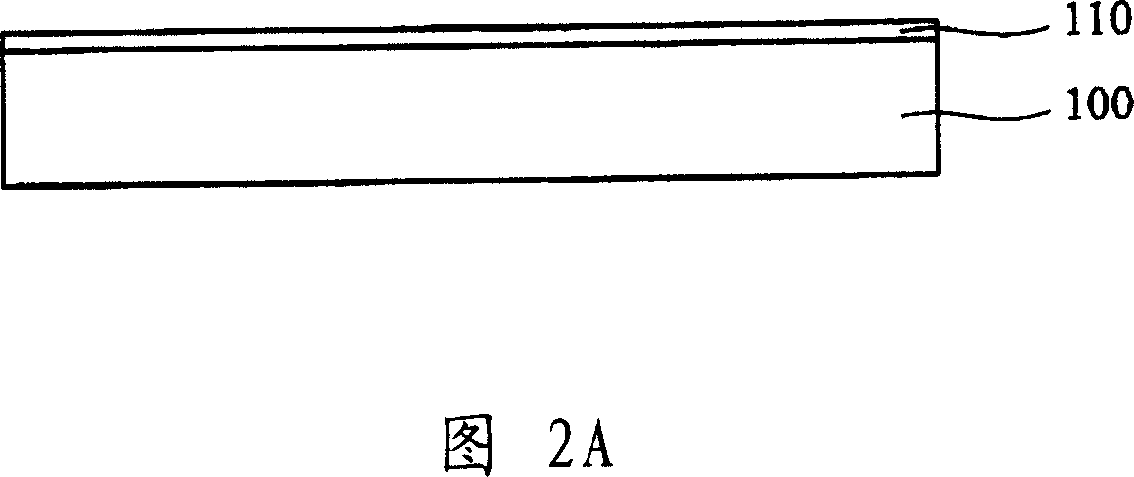
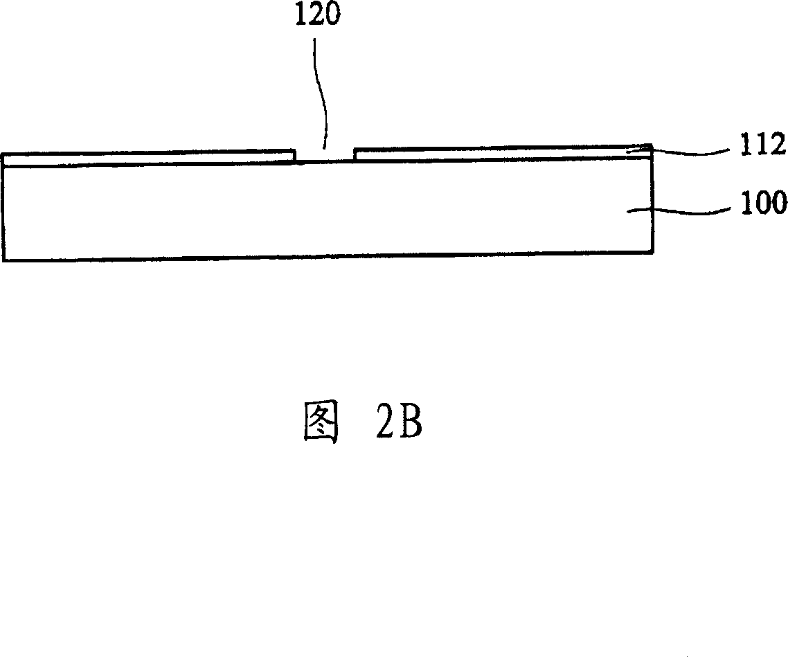
[0040] 2A-2H are schematic cross-sectional views showing a method of fabricating a fluid ejection device according to an embodiment of the present invention. First please refer to FIG. 2A, a shielding layer 110 is formed on a first substrate 100, wherein the first substrate is preferably made o...


PUM


Abstract

The invention relates to a composite energy saving decorative board and its manufacturing method. It forms the etching stop layer on the first liner of the concave, combines the stop layer to the second liner surface to form a cavity chamber between the etching layer and the second liner, then remove the first liner. After removing the first liner, form outside frame on the second liner to form the fluid ejection device. It can form the first, the second and the third oxidization layers on the etching stop layer and inside the chamber. Thanks to this device, it can increase isolation, reduce thermal crosstalk and improve its heat utilization rate and ink jet effect.

Description

technical field [0001] The invention relates to a fluid injection device and a manufacturing method thereof, in particular to a fluid injection device and a manufacturing method thereof that increase heat utilization rate and reduce thermal crosstalk. Background technique [0002] Due to continuous breakthroughs and innovations in the printing technology of liquid jet printers, the requirements for printing quality and resolution continue to increase. The demand for increasing the reliability of the inkjet head chip packaging components, the density of the nozzle holes and reducing the size of the components is also increasing. The thermal bubble inkjet head chip heats the ink in the fluid chamber through the heating element, so that the ink is heated to generate bubbles and then push the ink out. After the ink drop is ejected, the temperature decreases immediately, and the temperature in the fluid chamber also decreases, and then the protruding ink is pulled back into the ...

Claims


Application Information

Patent Timeline
IPC IPC(8): B41J2/14B41J2/16B41J2/05
Inventor 庄文宾周忠诚
Owner BENQ CORP
Why Eureka
Try Eureka