Lens used for LED light source

A technology of LED light source and LED chip, applied in the direction of lens, optics, optical components, etc., can solve the problems that cannot meet the needs of semiconductor lighting

Inactive Publication Date: 2007-11-07
TSINGHUA UNIV
View PDF4 Cites 53 Cited by
  • Summary
  • Abstract
  • Description
  • Claims
  • Application Information

AI Technical Summary

Problems solved by technology

[0006] To sum up, the structure of LED packaging lens at this stage cannot meet the needs of semiconductor lighting. It is necessary to design a lens with h

Method used


Image

  • Lens used for LED light source
  • Lens used for LED light source
  • Lens used for LED light source

Examples


Embodiment Construction

[0030] The present invention will be further described through the embodiments below in conjunction with the accompanying drawings.

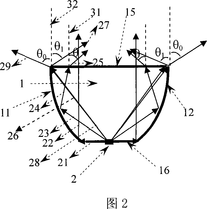
[0031] The critical condition for total internal reflection of light at the lens medium-air interface is:

[0032] θic = arcsinl / n,

[0033] where n is the refractive index of the lens medium.

[0034] When the incident angle θi of light satisfies

[0035] θi≥θic

[0036] When , light is totally internally reflected at the lens medium-air interface, and this condition is referred to as the total internal reflection condition hereinafter. When light is totally internally reflected, the law of reflection is followed, that is, the angle of reflection is equal to the angle of incidence.

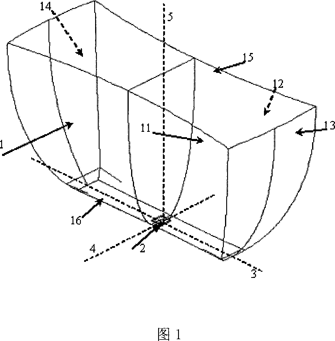
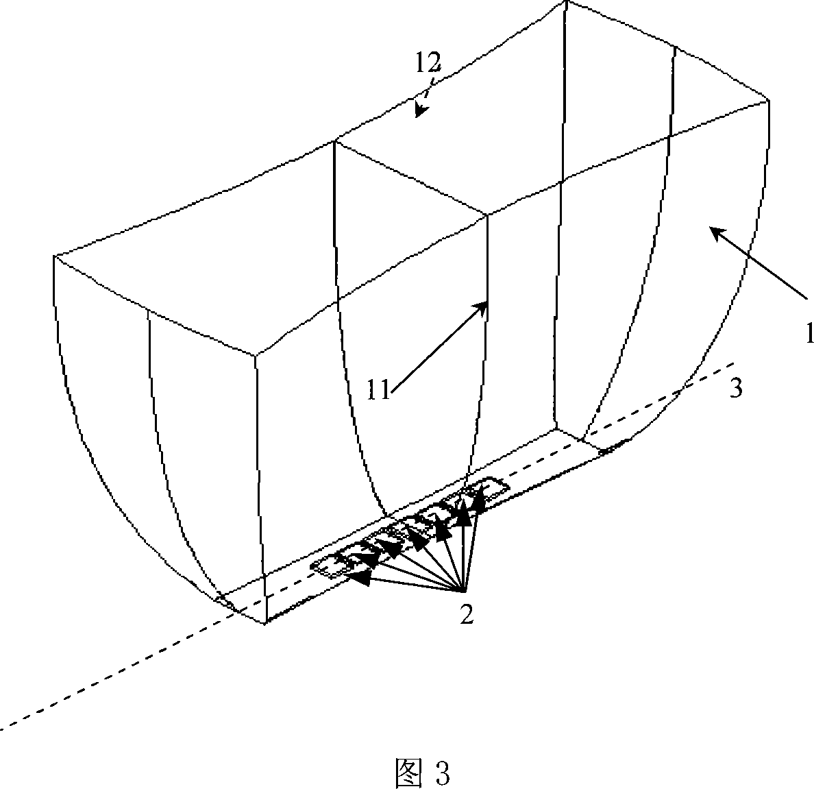
[0037] The basic structure of the LED lens 1 for forming a strip-shaped spot disclosed by the present invention is shown in FIG. 1 . The lens 1 described in Fig. 1 contains two pairs of 11 and 12, 13 and 14 designed curved surfaces with limited light effects a...


PUM


Abstract

The invention relates to a lens used in LED light source. It includes one upper surface, four side faces, and one under surface. The upper one is light emergent face. The under one is LED light source incidence face. The four side faces is formed by two pairs of symmetroids which can make the incident light occur total internal reflection and the angle theta c between the emergence light projection on the cross section and the upper surface normal direction. The incident light on the side face can be reflected to refract out of the lens. Thus the light radiated from the LED light source can form an illumination range with rectangle, square, or strip on far field though the lens.

Description

technical field [0001] The invention relates to a lens for an LED light source, the purpose of which is to limit the light emitted by an LED chip to exit within a certain angle and form a strip, rectangle or square illumination range, which belongs to the technical field of light emitting diode packaging and application. Background technique [0002] The high-power LED chips developed rapidly in recent years can be used for lighting. Its luminous efficiency has surpassed incandescent lamps. Compared with fluorescent lamps, it has the advantages of green light sources: that is, it does not contain lead, mercury, ultraviolet light, and flicker. Since LED has significant advantages such as small size, high efficiency, energy saving, environmental protection, long service life, fast response, vibration resistance, and easy maintenance, it is bound to be used in the field of lighting. The lighting designed according to the characteristics of LED is also changing with each passing...

Claims


Application Information

Patent Timeline
IPC IPC(8): G02B3/00G02B27/00H01L33/00H01L33/58
Inventor 罗毅赵小莹韩彦军钱可元
Owner TSINGHUA UNIV
Why Eureka
Try Eureka