Systems and methods for low-temperature gas separation

A low-temperature, hydrocarbon gas technology, applied in the field of low-temperature gas separation systems, can solve problems such as high energy consumption and pressure loss of mixtures

Inactive Publication Date: 2007-11-07
3S GAS TECH LTD
View PDF6 Cites 14 Cited by
  • Summary
  • Abstract
  • Description
  • Claims
  • Application Information

AI Technical Summary

Problems solved by technology

[0008] The fundamental disadvantages of these cryogenic gas separators are the significant mixture pressure loss and high energy consumption during cryogenic gas separation

Method used


Image

  • Systems and methods for low-temperature gas separation
  • Systems and methods for low-temperature gas separation
  • Systems and methods for low-temperature gas separation

Examples


Embodiment Construction

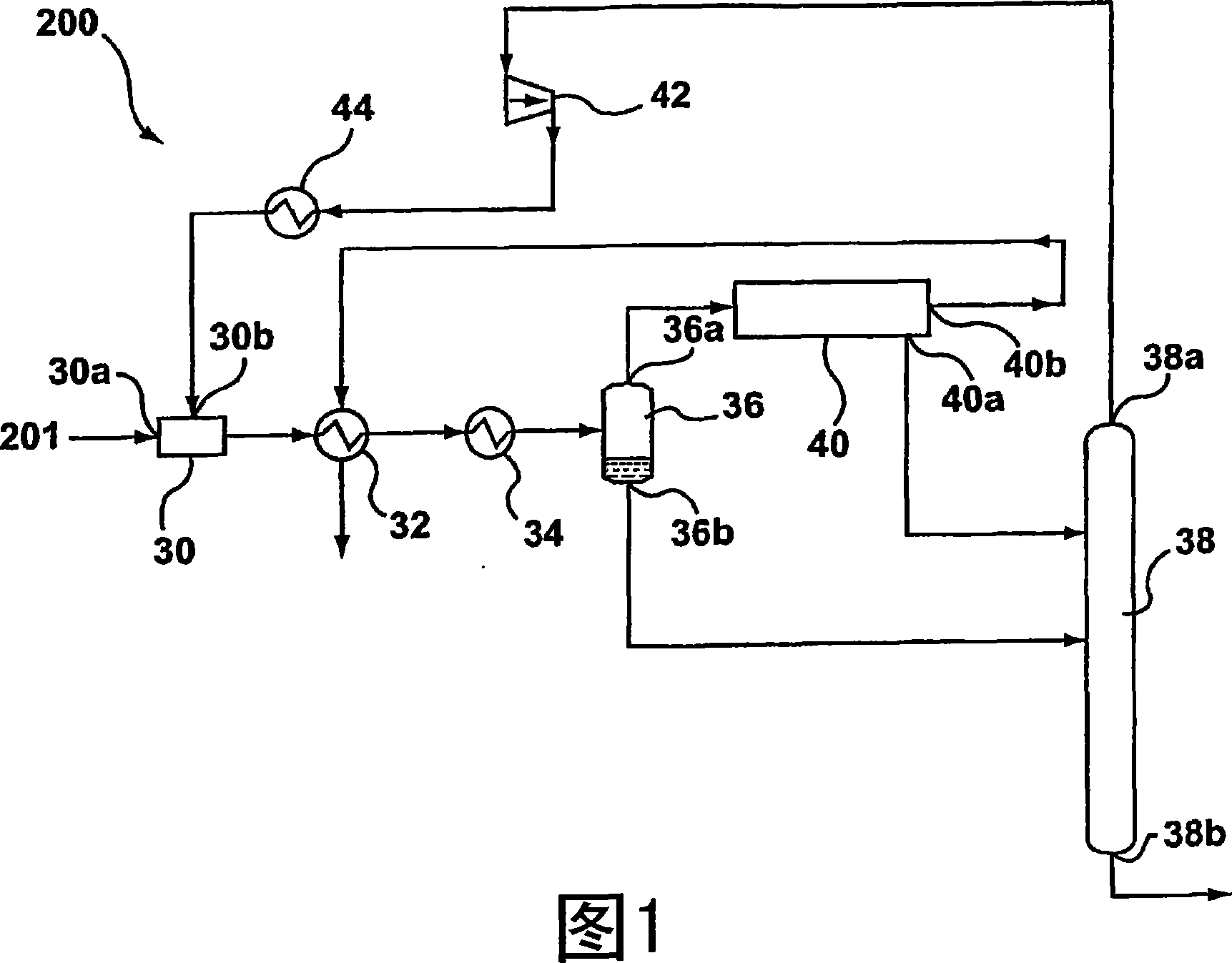
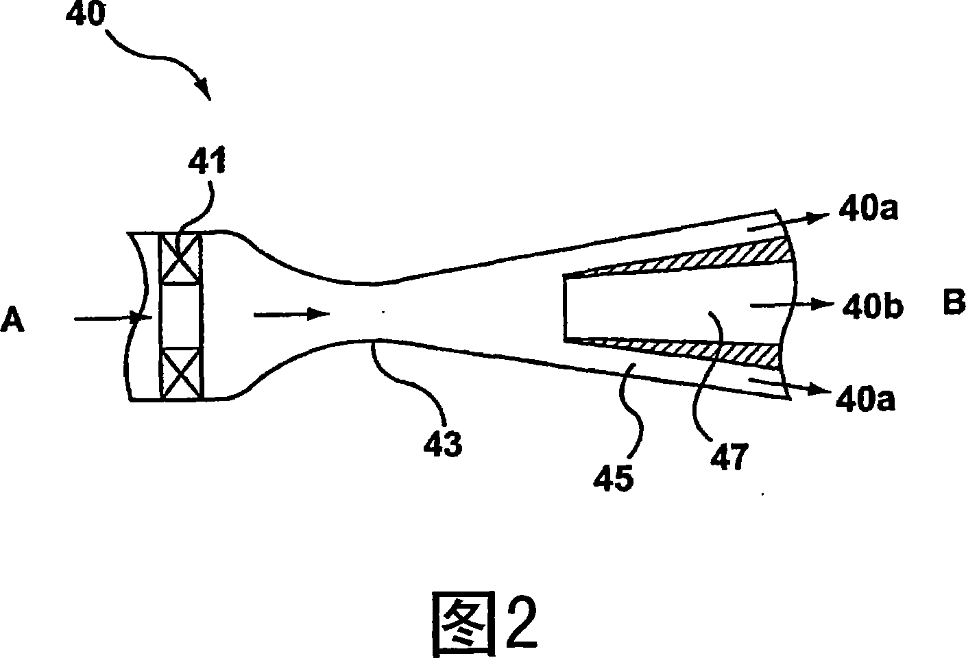
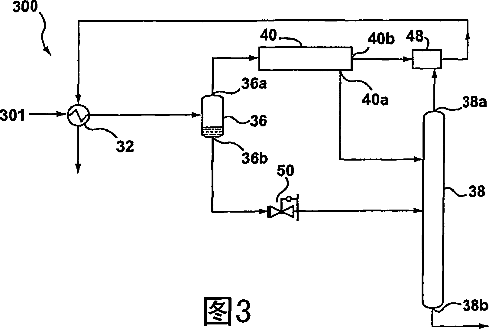
[0072] Some embodiments of the invention can reduce power consumption in LTS facilities. With regard to this aim, according to some embodiments of the invention, it can be achieved in the first embodiment of the invention due to the fact that in the known LTS process for hydrocarbon gas mixtures, it consists of cooling the mixture, without doing mechanical expansion of the mixture or a part thereof, partial condensation of the mixture during its expansion, separation of the mixture or a part thereof in a rectification column to obtain liquid and gas phase products, according to the invention the expansion of the mixture is achieved by passing the mixture through a nozzle channel whereby the mixture stream is swirled in the nozzle channel and / or at the inlet of the nozzle channel, and at the outlet of the nozzle channel or a portion thereof the mixture stream is split into at least two streams, one stream being enriched in methane heavy components, while the other stream is def...


PUM


Abstract

Disclosed is a method of gasifying a biomass, comprising heating a fluidized bed reactor loaded with a catalyst represented by Rh / CeO2 / M, where M represents SiO2, Al2O3 or ZrO2, to temperatures lower than 800 DEG C. introducing biomass particles into the fluidized bed reactor from an upper portion thereof, introducing air and steam into the fluidized bed reactor from a lower portion thereof, and allowing the biomass particles to react at the surface of the Rh / CeO2 / M catalyst so as to manufacture hydrogen and a syngas.

Description

[0001] priority claim [0002] This application claims the benefit of Russian Patent Application No. 2004128348 / 06 (030834), filed September 24, 2004, which is incorporated herein by reference in its entirety. technical field [0003] The present invention relates to gas separation technology, and in particular systems and methods for cryogenic gas separation. Background technique [0004] Existing methods for the cryogenic separation of target components from gas mixtures are based on freezing of the gas mixture, condensation of the target component, and subsequent separation of the condensate containing the target component from the gas mixture. The freezing of the gas mixture in this method is conventionally carried out at the expense of a throttle valve and expansion of the gas in an expander, or by means of a refrigeration device. In the solution of cryogenic gas separation, recuperators and rectification towers are used as additional auxiliary equipment. [0005] Typ...

Claims


Application Information

Patent Timeline
Patent Type & Authority Applications(China)
IPC IPC(8): F25J3/02B01D5/00C10G7/00B01D3/00
CPCB01D5/0033B01D5/0045F25J3/0209F25J3/0233F25J3/0238F25J2200/02F25J2200/70F25J2200/76F25J2205/04F25J2205/10F25J2210/04F25J2230/08F25J2230/60F25J2240/02F25J2240/60F25J2245/02F25J2270/02F25J2270/04F25J2270/90F25J2270/88B01D3/00B01D5/00C10G7/00F25J3/02
Inventor V·I·阿尔费罗夫L·A·巴吉罗夫V·I·费金S·Z·伊迈夫L·M·德米特里耶夫
Owner 3S GAS TECH LTD
Why Eureka
Try Eureka