Fibre decomposite and fibre de-composition apparatus

A fiberizing machine and fiberizing technology, applied in the direction of raw material separation, etc., can solve the problems of large vibration noise, large dust, unfavorable molding, etc., and achieve the effect of reducing power consumption, reducing vibration noise, and improving crushing capacity

Active Publication Date: 2007-11-21
HANGZHOU XINYUHONG INTELLIGENT EQUIP CO LTD
View PDF1 Cites 15 Cited by
  • Summary
  • Abstract
  • Description
  • Claims
  • Application Information

AI Technical Summary

Problems solved by technology

[0003] In terms of structural design, the existing raw material defiberizing machine for sanitary products, one is that the cutter head is an upward rotation type, not only when the cutter head is working, not only the dust is large, but also the pollution to the environment is very large; the second is that the cutter head of the cutter head is The saw-tooth type left and right split-bending in-line structure not only consumes a lot of power, but also has poor crushing capacity and large vibration noise; the third is single-layer feeding, which not only has a large volume of the defibrating machine, high manufacturing cost, but also high power consumption; The material port is an inclined discharge port, which is not conducive to forming

Method used


Image

  • Fibre decomposite and fibre de-composition apparatus
  • Fibre decomposite and fibre de-composition apparatus
  • Fibre decomposite and fibre de-composition apparatus

Examples


Embodiment 1

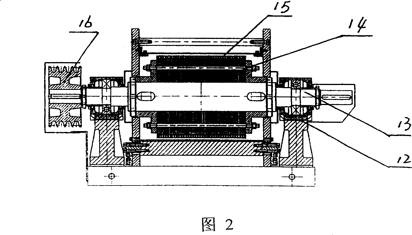
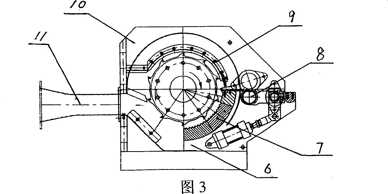
[0018] Embodiment 1: with reference to accompanying drawing 1~3 and Fig. 8 and Fig. 9. For the defibrated body, the discharge port 11 communicates with the pulverized body, and the pulverized system is in the prior art, so it will not be described here. The cutter head 14 is located in the cutter box plate 10 through the main shaft 13, the main shaft 13 is supported by the bearing housing 12, the belt pulley 16 is located at one end of the main shaft 13, and the fixed tooth block 7 is located at the lower part of the cutter head 14 between the cutter box plates and is in clearance fit with the cutter head. The feeding assembly 8 is located between the arc-shaped sealing plate 9 and the fixed tooth block 7, and the discharge port is directly facing the cutter head 14. The bottom of the plurality of cutter heads 15 of the blade 54 is a concave arc-shaped groove 54. The cutter head 14 is composed of multiple The blades 54 are flat stacked and the cutter heads 15 of the multi-blad...

Embodiment 2

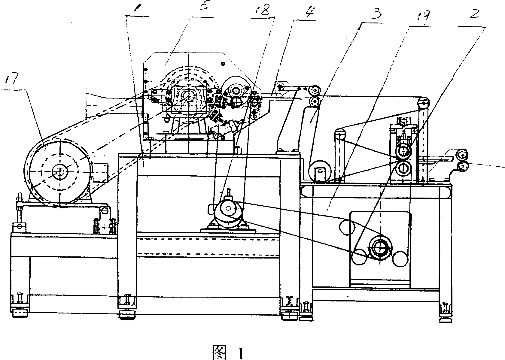
[0019] Embodiment 2: with reference to accompanying drawing 1~8. A defibrating machine composed of a defibrating body, which includes a frame 1, a defibrating body 5, a main shaft drive motor 17, a conveying mechanism driving motor 18 and a conveying mechanism 19, the defibrating body 5 is located on the frame 1, and the pulp plate folding mechanism 3 is located in front of the double-layer feeding port of the defibrating body 5 and is located on the frame 1, the cutting knife assembly 2 is located in front of the pulp plate folding mechanism 3 and is located on the frame 1, and the cutting knife assembly 2 is transported by the conveying mechanism The drive motor 18 and the transmission mechanism drive the cutting knife assembly 2 to cut the knife and transport the cut sheet to the pulp sheet folding mechanism 3 through the conveying mechanism 19, and then fold it into double layers through the pulp sheet folding mechanism and then pass through the defibrating body 5 The feed...


PUM


Abstract

This invention relates to fiber solute body and its machine for producing treatment, half treatment and un-treatment pulp slurry. The fiber solute body is on the materials shelf, pulpboard folding agencies is in the front of double feed month, slitting knife assembly is in the in the front of pulpboard folding agencies, both the slitting knife assembly and pulpboard folding agencies are on the materials shelf. The motor in slitting knife assembly is driven by transportation agency, the knife in slitting knife assembly is driven by Drive agency, the slitting plate is sent to pulpboard folding agencies by the transportation agencies, and then to be made into a double-decker by pulpboard folding agencies, finally be sent to the fiber solute body by feeding assembly to solute fiber. The advantages are as follows: Firstly, effectively reduce dust pollution to achieve the purpose of environmental protection; secondly, not only reduce the volume of fiber, and greatly reduced the consumption of electric power; thirdly, not only improve its crushing capacity, but also significantly reduces vibration noise, raise its forming rate.

Description

technical field [0001] The invention relates to a defibrating body and a defibrating machine for producing treated pulp, semi-treated pulp and untreated pulp, and belongs to the field of sanitary product auxiliary equipment manufacturing. Background technique [0002] Patent No. 01252738.6, titled "Wood pulp board defibrillator", the wood pulp board defibrator has a frame (13), guide rollers (2) fixed on it, quantitative feeding rollers (3), feeding Pressing roller (4), the fixed knife plate (12) below the feeding press roller, and the defibrating roller (6) with barbed teeth and the fiber collecting cover (7) surrounded outside the defibrating roller (6), collect The side of the fiber cover (7) close to the fixed knife plate (12) is composed of a feed port (5) and a fiber collection conveyor belt (11) located under the fiber collection cover. The fiber chamber (9), the lower end of the fiber collection cover (7) is shrunk to form a blanking opening (10), and the fiber coll...

Claims


Application Information

Patent Timeline
Patent Type & Authority Applications(China)
IPC IPC(8): D21B1/06
Inventor 翁琦清项逊华
Owner HANGZHOU XINYUHONG INTELLIGENT EQUIP CO LTD
Why Eureka
Try Eureka