Electronic thermometer
An electronic thermometer and circuit technology, applied in thermometers, body temperature measurement, thermometer applications, etc., can solve problems such as rising costs, and achieve the effects of eliminating dimensional errors, reducing dimensional accuracy and assembly accuracy
- Summary
- Abstract
- Description
- Claims
- Application Information
AI Technical Summary
Problems solved by technology
Method used
Image
Examples
Embodiment 1
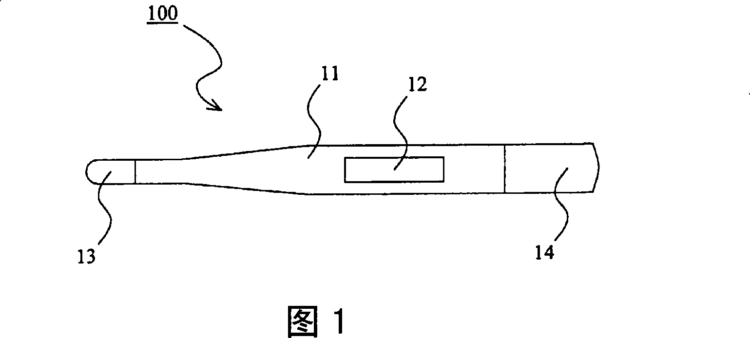
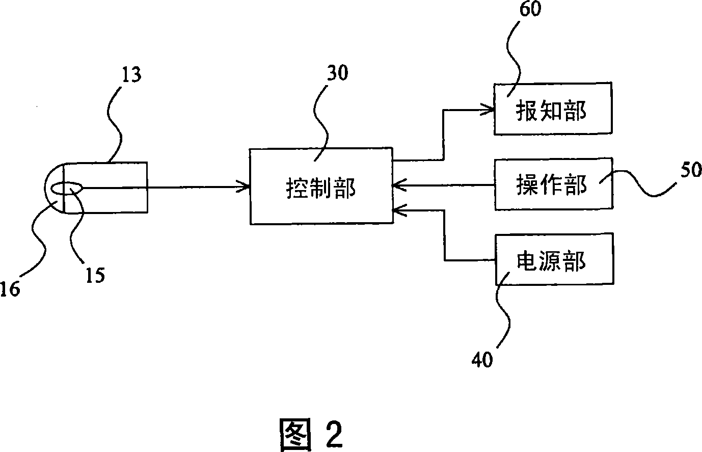
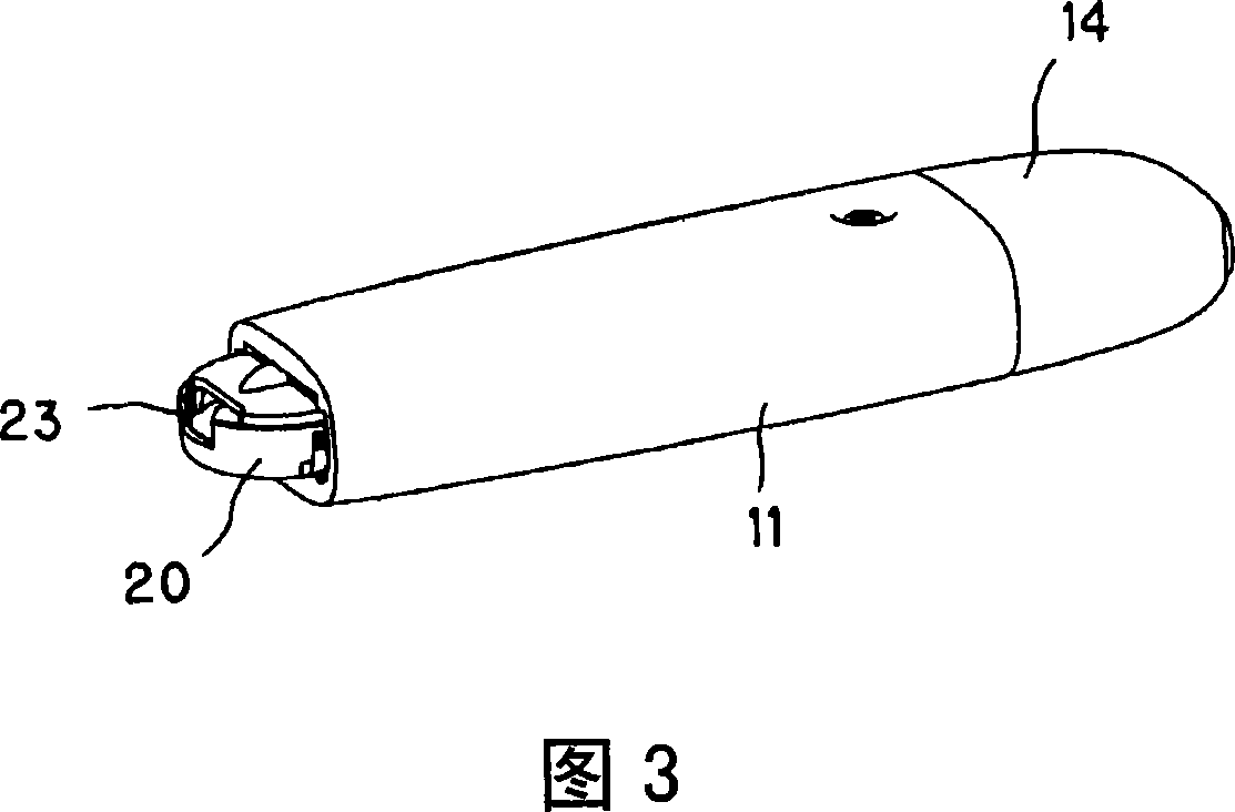
[0054] An electronic thermometer according to Example 1 of the present invention will be described with reference to FIGS. 1 to 9 . FIG. 1 is a plan view of an electronic thermometer according to Embodiment 1 of the present invention. Fig. 2 is a block diagram of an electronic thermometer according to Embodiment 1 of the present invention. 3 is a partially cutaway perspective view of the electronic thermometer according to Embodiment 1 of the present invention. Fig. 4 is a perspective view showing a state in which various components are assembled in the inner case according to the first embodiment of the present invention. 5 is a perspective view showing a state in which a buzzer and a buzzer cover (pressing member) are assembled in an inner case according to Embodiment 1 of the present invention. Fig. 6 is a six-sided view of the buzzer cover in Embodiment 1 of the present invention. Fig. 7 is a diagram showing a fixing structure of a buzzer according to Embodiment 1 of th...
Embodiment 2
[0078] Fig. 10 shows Embodiment 2 of the present invention. In this embodiment, a modified example of the buzzer cover as the pressing member is shown. Since other structures and functions are the same as those in Embodiment 1, the same symbols are assigned to the same structural parts, and their descriptions are omitted. Fig. 10 is a schematic diagram of a buzzer cover according to Embodiment 2 of the present invention. In addition, FIG. 10( a ) is its top view, and FIG. 10( b ) is its cross-sectional view (AA cross-sectional view in FIG. 10( a )).
[0079] The buzzer cover 70a of the present embodiment is also made of a material such as resin and has flexibility, as in the first embodiment. Moreover, this buzzer cover 70a has: a disc-shaped body portion 71a, a protruding portion 72a provided in the center of the body portion 71a, a substantially cylindrical pressing portion 73a provided along the edge of the body portion 71a, and a pressing portion 73a for pressing. A pai...
Embodiment 3
[0085] Fig. 11 shows Embodiment 3 of the present invention. In the cases shown in the first and second embodiments, the buzzer cover as the pressing member is provided with a protruding portion, and the buzzer cover bends when the protruding portion abuts against the inner wall surface of the outer case. In the case shown in this embodiment, a protruding portion is provided on the inner wall surface of the outer casing, and the buzzer cover is bent by the protruding portion. The other structures and functions are the same as those in Embodiment 1, so the same symbols are assigned to the same structural parts, and their descriptions are omitted. 11 is a part of a cross-sectional view in the longitudinal direction of an electronic thermometer according to Example 3 of the present invention. Furthermore, FIG. 11 shows a cross section at the same position as in FIG. 9 in the first embodiment.
[0086] The buzzer cover 70b of this embodiment differs only in that the buzzer cover ...
PUM
 Abstract
Description
Claims
Application Information
 - R&D
- Intellectual Property
- Life Sciences
- Materials
- Tech Scout
- Unparalleled Data Quality
- Higher Quality Content
- 60% Fewer Hallucinations
Browse by: Latest US Patents, China's latest patents, Technical Efficacy Thesaurus, Application Domain, Technology Topic, Popular Technical Reports.
© 2025 PatSnap. All rights reserved.Legal|Privacy policy|Modern Slavery Act Transparency Statement|Sitemap|About US| Contact US: help@patsnap.com


