Method and apparatus for correcting multi-screen connected wall

A technology of a correction device and a correction method, which is applied to the image reproducer of a projection device, a color TV, an instrument, etc., can solve the problems of poor versatility, increased time-consuming correction, and large error.

Inactive Publication Date: 2007-11-21
GUANGDONG VTRON TECH CO LTD
View PDF1 Cites 101 Cited by
  • Summary
  • Abstract
  • Description
  • Claims
  • Application Information

AI Technical Summary

Problems solved by technology

The process is complex and the amount of data is very large. The number of acquisitions for a single display unit to establish mapping data is 3*256=768 times, and the calibration process may require multiple iterations. As the number of channels increases, the calibration time will increase correspondingly.
In addition, the system needs color

Method used


Image

  • Method and apparatus for correcting multi-screen connected wall
  • Method and apparatus for correcting multi-screen connected wall
  • Method and apparatus for correcting multi-screen connected wall

Examples


Embodiment 1

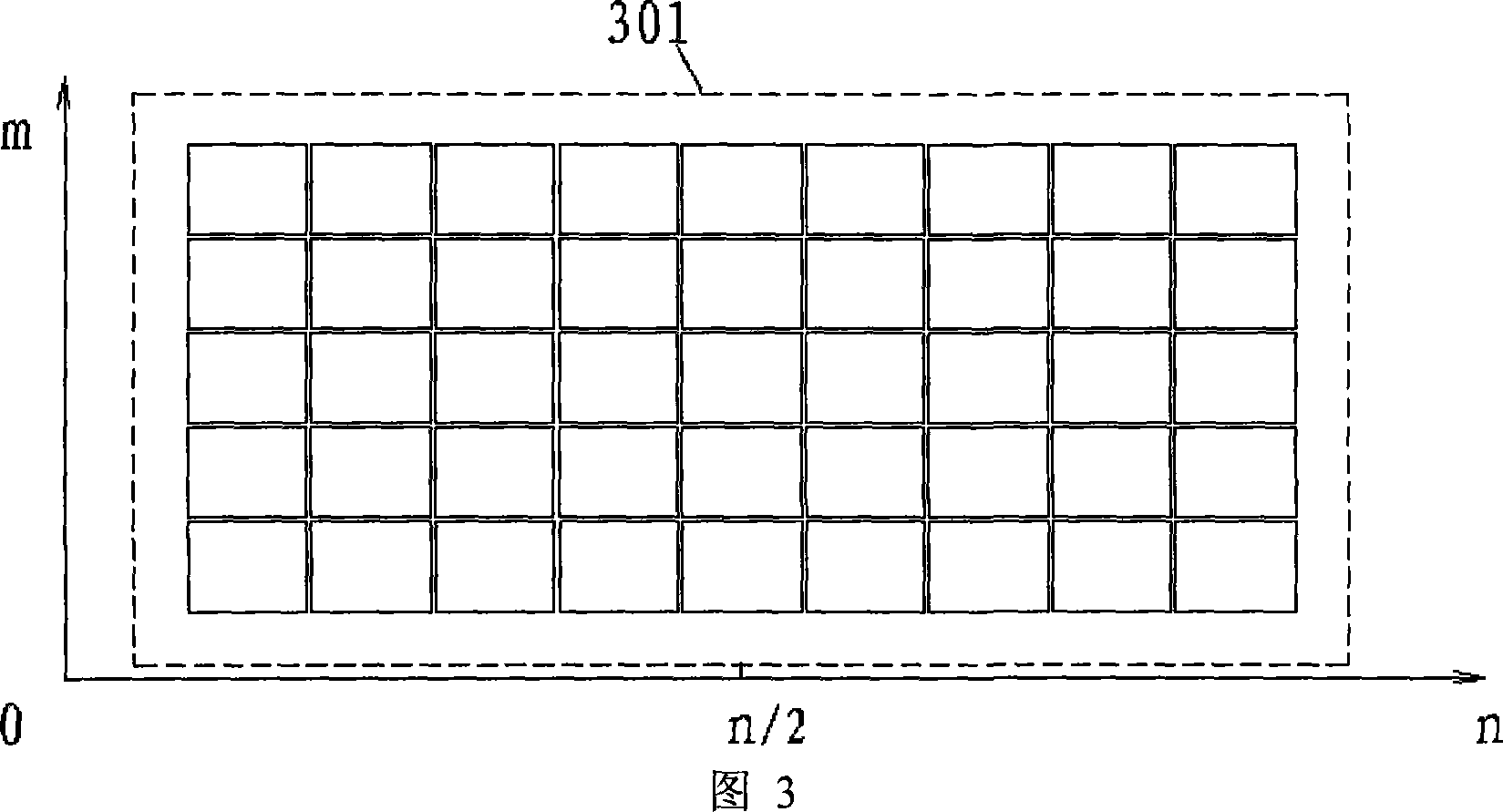
[0051] m×n (m: the number of rows that make up a multi-screen wall, n: the number of columns that make up a multi-screen wall) the schematic diagram of the multi-screen color correction method is shown in Figure 4, and the calibration device can be placed in front of the screen to capture the entire display area 401, control the display screen to display a picture of a specified color, take a picture of the screen, extract the color information of the display unit from the picture, and use the central display unit 402 as a reference to adjust synchronously in four directions 403, 404, 405, 406, and then in The inner edges of each small area are adjusted from the inside to the outside, such as 407, 408, 409, 410 and so on. The unadjusted display unit is adjusted step by step based on the adjusted display unit, and the adjusted display unit can be properly adjusted as required.

[0052] The computer sends commands to the calibration device to control the video wall to display a ...

Embodiment 2

[0058] The schematic diagram of the multi-screen wall color method of partition correction m×n is shown in Figure 5. The screen is divided into four 501, 502, 503, 504 or more correction areas, and every two adjacent correction areas overlap one row or one column of display units. The four-region correction method is as follows:

[0059] First area correction: In Figure 6, 601 is the first correction area, 602 is the reference display unit, step by step correction to the left along the row where 602 is located, upward correction along the column where 602 is located, and use the corrected display unit as a new reference , gradually correct its adjacent display units, and finally correct 601 the entire display area.

[0060] Second area calibration: 701 in Figure 7 is the second calibration area, and the display unit in the column 702 is the overlapping area between 701 and the calibration area 601 in Figure 6, and the display unit in this column has been corrected in the calib...


PUM


Abstract

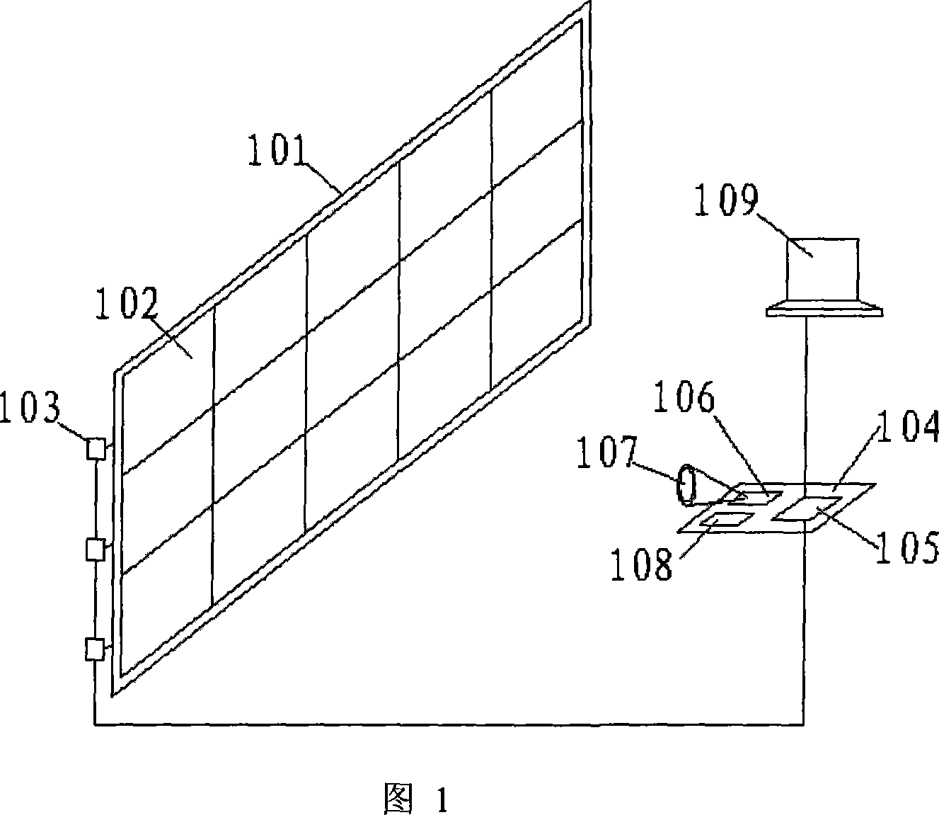
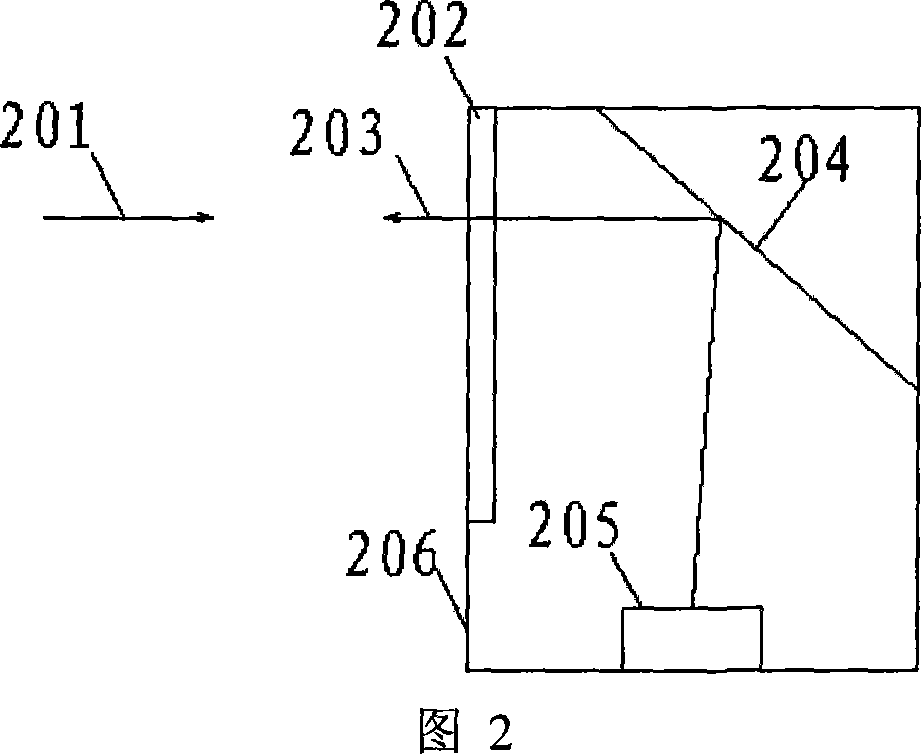
The apparatus comprises a correction unit composed of a video camera module for capturing the color information of the screen, an image data buffer module, and a main control module used for receiving and executing the computer command. Said video camera module and image data buffer module are respectively connected to the multi-screen display wall and computer via the main control module. The method comprises: appointing the image displayed by each display unit on the multi-screen display wall; said video camera module shoots at least one picture and saves it in the image data buffer module; the computer extracts the color information from each display unit; according to the color of each display unit, the computer corrects the difference between said display units.

Description

technical field [0001] The present invention relates to a calibration device and method for a display device, in particular to a multi-screen video wall calibration device and method. Background technique [0002] With the development of computer information technology, the demand for multi-screen display equipment and technology in the fields of China Telecom, electric power, water conservancy, public security, urban transportation, road transportation and industrial production process monitoring has grown rapidly. The multi-screen digital video wall system can combine various Computer signals and video signals are displayed on the multi-screen splicing wall to form a set of information display management and control system with complete functions and advanced technology, providing users with an interactive man-machine interface, which can fully meet the real-time and multi-screen requirements of the dispatching command center. Show need. However, the consistent correction...

Claims


Application Information

Patent Timeline
IPC IPC(8): H04N9/31G09G5/02
CPCH04N9/3197G09G2360/147G09G2320/0242G06F3/1446H04N9/3194G09G2320/0285H04N9/3147
Inventor 卢如西徐响林
Owner GUANGDONG VTRON TECH CO LTD
Why Eureka
Try Eureka