Supercritical fluid continuous yarn dyeing instrument

A technology of supercritical fluid and dyeing yarn, applied in liquid/gas/vapor yarn/filament processing, dyeing method, liquid/gas/vapor processing of textile materials of a certain length, etc., can solve the problem of increasing device and control complexity, It is difficult to ensure uniformity, low production efficiency, etc., to achieve the effect of improving production efficiency and dyeing quality, reducing energy consumption and saving costs

Inactive Publication Date: 2007-11-28
SHANDONG UNIV
View PDF0 Cites 13 Cited by
  • Summary
  • Abstract
  • Description
  • Claims
  • Application Information

AI Technical Summary

Problems solved by technology

At present, there are two common structures in supercritical fluid yarn dyeing devices at home and abroad: one is to set a porous warp beam in the yarn dyeing device, the yarn to be dyed is wound on the shaft, and the dyeing fluid passes through the warp beam in one direction. The yarn is dyed. This structure is difficult to ensure the uniformity of dyeing of each layer of yarn; the other is that the dyeing fluid passes through the fabric alternately from the inside to the outside and from the outside to the inside to achieve the purpose of uniform dyeing. This structure requires a The reversing pipeline of the dyed fluid increases the complexity of the installation and control
What is more critical is that both of the above two types are of intermittent structure, that is, after each batch of yarn is dyed, it must go through the process of reducing pressure, taking yarn and restarting. This structure leads to complicated process, large energy consumption and low production efficiency.

Method used


Image

  • Supercritical fluid continuous yarn dyeing instrument
  • Supercritical fluid continuous yarn dyeing instrument
  • Supercritical fluid continuous yarn dyeing instrument

Examples


Embodiment Construction

[0021] The best embodiment of the present invention will be described in detail with reference to the accompanying drawings.

[0022] As shown in Figure 1, Figure 2 and Figure 3:

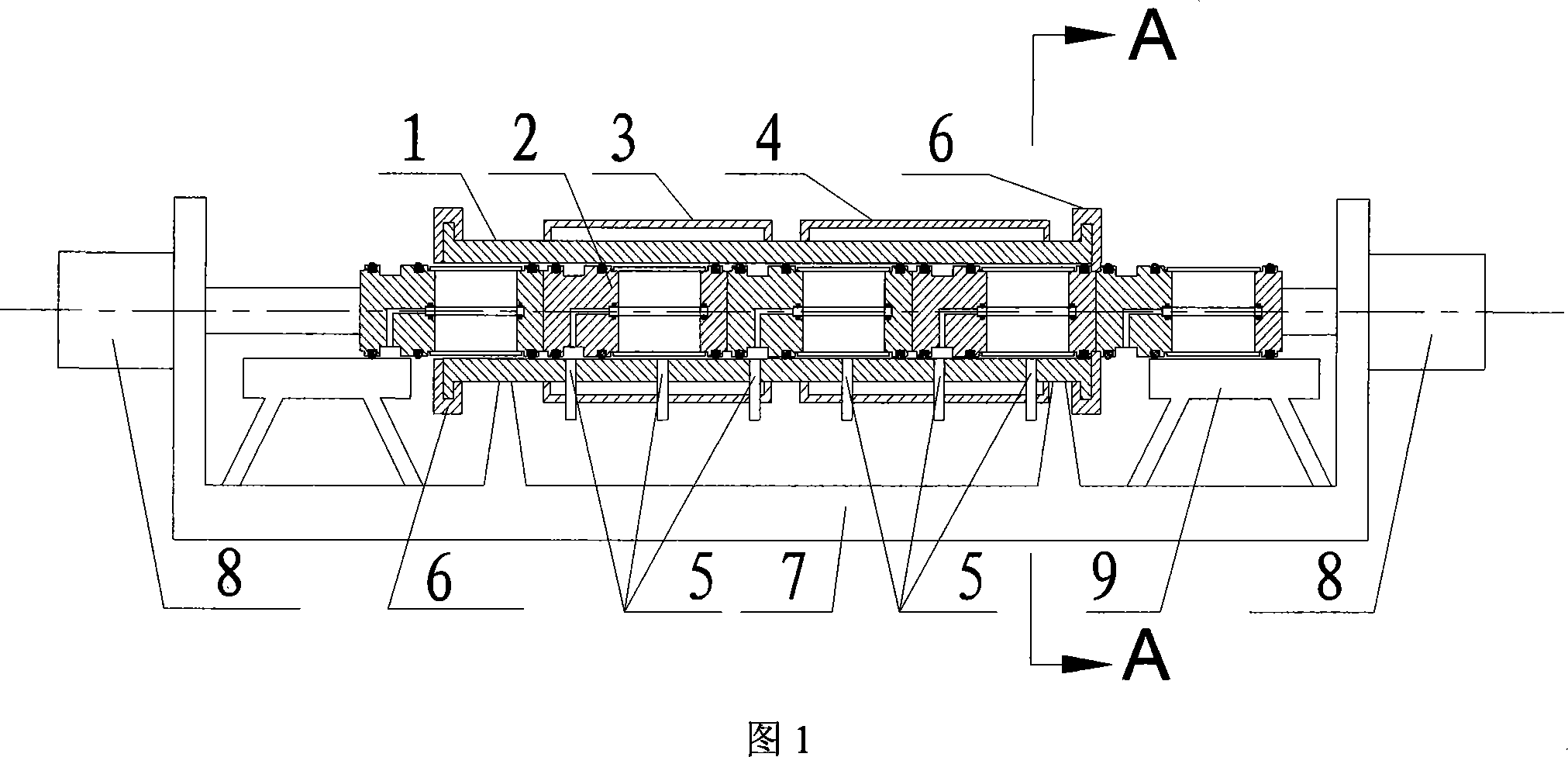
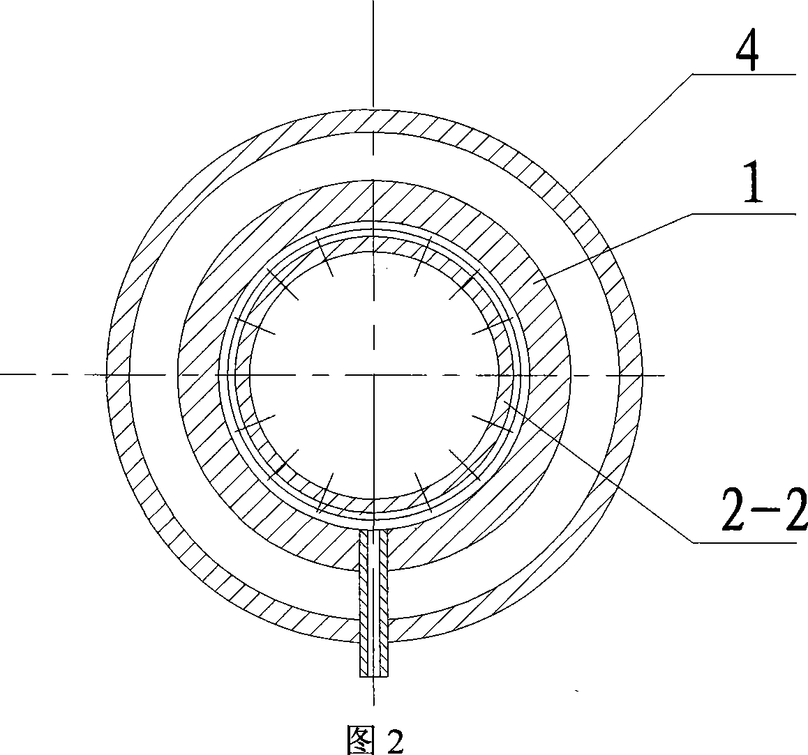
[0023] The cylinder body 1 of the yarn dyeing device is installed on the base 7, and there is a fluid pipeline interface 5 on the cylinder body 1, and heaters 3 and 4 are installed outside the cylinder body 1; Installed at both ends of the barrel 1; the driving mechanism 8 is installed at both ends of the base 7, and the power output part corresponds to the yarn bin 2 entering and leaving the barrel 1; the yarn bin bracket 9 is installed at the inlet and outlet of the barrel 1 , supporting the yarn bin 2 that goes in and out of the barrel 1.

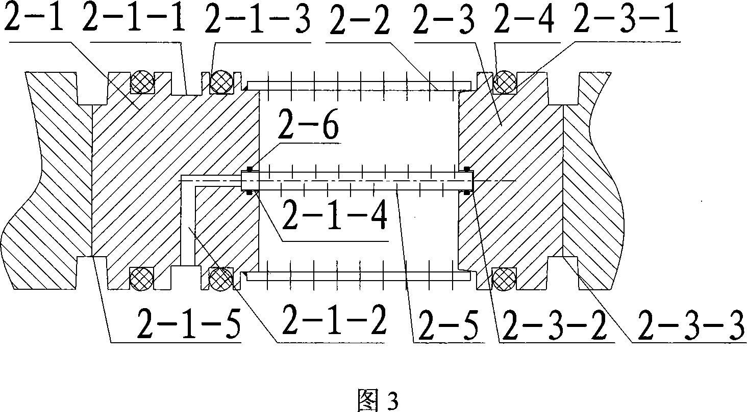
[0024] The yarn bin 2 is composed of a yarn bin base 2-1, a fluid distribution cylinder 2-2, an end cover 2-3, a seal 2-4, a bobbin 2-5 and a seal 2-6; the yarn bin base 2- The seal 2-4 in the sealing groove 2-1-3 of 1 is sealed with at least two metal or po...


PUM


Abstract

This invention belongs to the dyeing device for the fibre, yarn and textile, it especially relates to the super critical fluid continuously yarn dyeing machine of the device. It consists of the cavity body, yarn storehouse, heater, cut-off device for the yarn storehouse, basement, driving configure and bracket of the yarn storehouse. The cavity body installs on the basement, the outside of the body is heater, and there is pipe interface for the fluid on the cavity body. The yarn storehouse sets up in the cavity, the cut-off device installs on the both sides of the cavity. The driving configure installs two sides of the basement, and the momentum output device is corresponding to the yarn storehouse inside the cavity, and the bracket of the yarn storehouse fixes on the inlet of the cavity. The structure of this invention is rational, the controlling is simple, and it realize the continuously operation of dyeing and cleaning the float color at the sealing high pressure condition.

Description

1. Technical field [0001] The invention belongs to the field of dyeing devices for fibers, yarns and fabrics, in particular to a supercritical fluid continuous yarn dyeing device in the dyeing device. 2. Background technology [0002] Supercritical fluid dyeing, especially supercritical carbon dioxide dyeing, uses supercritical fluid instead of water as the carrier of dyestuff, thus fundamentally solving the problem of water pollution in the dyeing industry. This process has broad application prospects. [0003] The supercritical fluid dyeing machine is the core equipment of the supercritical fluid dyeing device, and the advanced nature of the equipment affects the technological process and performance of the whole device. At present, there are two common structures in supercritical fluid dyeing devices at home and abroad: one is to set a porous warp beam in the yarn dyeing device, the yarn to be dyed is wound on the shaft, and the dyeing fluid passes through the warp beam i...

Claims


Application Information

Patent Timeline
Patent Type & Authority Applications(China)
IPC IPC(8): D06B23/00D06B3/04D06P1/94
CPCD06B5/16
Inventor 王威强郭德国王杰曲延鹏刘燕
Owner SHANDONG UNIV
Why Eureka
Try Eureka