[0002] At present, only one single ring is installed in each ring groove of traditional
internal combustion engine piston rings, and the openings of multiple gas rings are installed in misalignment. During the work of compressing gas, there is always axial air leakage at the opening of the piston ring. channels and radial air leakage channels, and as the engine’s working time continues, its air leakage channels will gradually increase, and the piston ring cannot be used after reaching a certain limit; there are also combined rings disclosed in
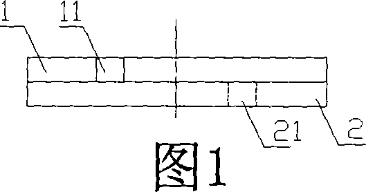
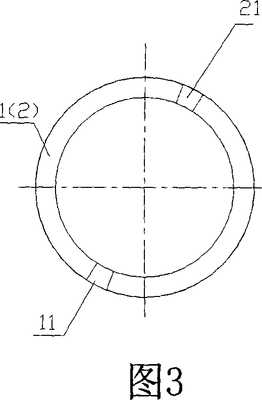
Chinese patent ZL90108400.X Structure, as shown in Figure 1 and Figure 3, the combined gas ring is composed of the upper component ring 1 and the lower component ring 2, the opening 11 of the upper component ring 1 and the opening 21 of the lower component ring 2 are installed on the same piston ring in a staggered manner In the groove, the upper component ring 1 overlaps the lower component ring 2. Although such a combined ring can effectively block the axial air leakage of the piston ring during initial installation, it cannot effectively block the radial air leakage of the piston ring. , due to the non-stop
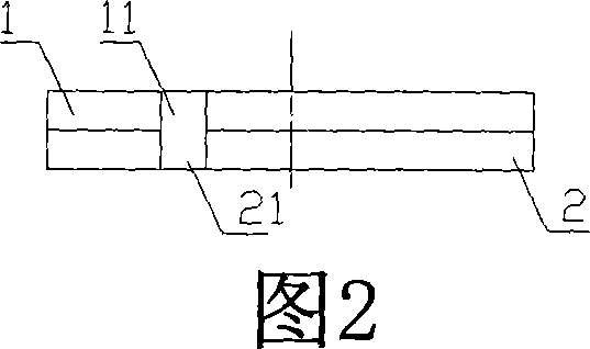
reciprocating motion of the piston, the piston ring will continue to rotate around the central axis of the piston in the piston groove, reaching the state shown in Figure 2 and Figure 4, that is, the opening 11 of the upper ring 1 and the lower ring 1 The openings 21 of the ring 2 overlap with each other, and because there is still a certain gap between the upper and lower rings, the combined piston rings form more serious axial and radial air leakage than those installed in the same piston ring groove. The air leakage of a piston ring is even more serious
[0003] Further, as disclosed in
Chinese patent ZL03263421.8, there is a technical solution for a combined gas ring with a sealing
interlocking device. This technical solution is to install a combined piston ring in the same piston ring groove. The combined piston ring includes an elastic The upper component ring and the lower component ring, the upper component ring is superimposed on the lower component ring, there is a sealing device and an
interlocking device between the upper and lower component rings, one of the component rings relies on the positioning piece welded on the surface of the body and the other component ring The grooves on the top are assembled and positioned to form a combination, so that the openings of the upper and lower rings are staggered from each other to block lateral air leakage; at the same time, the openings of the single-piece rings are radially blocked by the sealing piece, blocking the piston ring axial and Air leakage in two radial directions, but this combined gas ring with
interlocking device is close to the plane of the inner circle of the piston ring due to the fixed connection of the positioning pin. In this way, the piston ring is positioned on the
welding After pinning, the plane of the
welding positioning pin needs to be polished and processed, so that the plane of the piston ring itself lacks aesthetic feeling. At the same time, the
welding material may be polished off by mistake, which affects the firmness of the welding, increases the production process, time and cost, and makes the The quality stability of the production cannot be guaranteed. Moreover, the unevenness of the matching plane of the upper and lower rings will affect the matching relationship between the upper and lower rings. In addition, because the size of the piston ring is based on the exact size of the piston and
cylinder block It is determined by the comprehensive design of relative thermal change performance, once it is welded close to the inner circular end face, it will definitely cause the piston ring to have a large degree of
thermal deformation in the circumferential direction, destroying the original design function; in addition, the piston ring Due to the connection of the positioning pin and the sealing piece, the stress at the positioning pin and the sealing piece is relatively poor, and it is easy to deform. The positioning pin and the opening forming the ring on it, and the positioning groove and opening forming the ring below are usually In the installation state with a difference of 180 degrees or close to 180 degrees, in the process of compressing gas, the action of lateral high-pressure gas will easily cause the ring of the single-piece piston to bend and deform along the direction of the piston axis, resulting in poor smoothness of the piston ring, resulting in Leakage phenomenon

