Device, method and device for positioning the optical fiber failure

A technology for optical fiber fault and locating equipment, which is applied in the direction of testing optical fiber/optical waveguide equipment, optical fiber transmission, transmission monitoring/testing/fault measurement system, etc. Problems such as high system application cost to achieve the effect of reducing input cost and reducing operation difficulty

Active Publication Date: 2007-11-28
HUAWEI TECH CO LTD
View PDF0 Cites 43 Cited by
  • Summary
  • Abstract
  • Description
  • Claims
  • Application Information

AI Technical Summary

Problems solved by technology

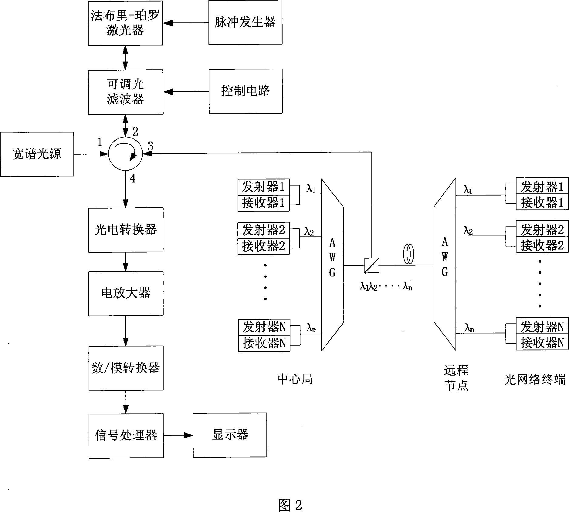
However, the traditional OTDR measurement method needs to adjust the tunable optical filter to dynamically align the central wavelength of the OTDR with the wavelength of the AWG (Array Waveguide Grating-Array Waveguide Grating) at the remote node in the system under

Method used


Image

  • Device, method and device for positioning the optical fiber failure
  • Device, method and device for positioning the optical fiber failure
  • Device, method and device for positioning the optical fiber failure

Examples


Embodiment Construction

[0028] In order to make the object, technical solution and advantages of the present invention clearer, the implementation manner of the present invention will be further described in detail below in conjunction with the accompanying drawings.

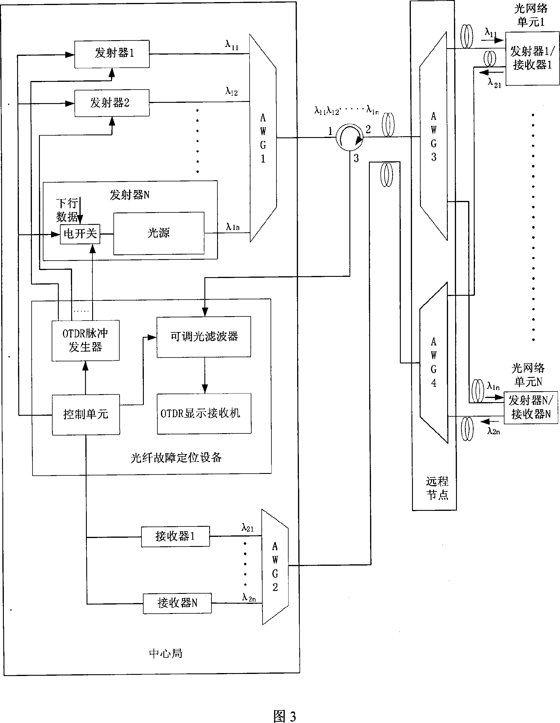
[0029]As shown in Figure 4, an embodiment of the present invention provides a fiber optic fault location device, which includes a light source, a pulse generator, a control circuit, an OTDR wavelength selection module, an output optical signal amplification and modulation module, a circulator, and a reflected optical signal receiving module : The OTDR wavelength selection module is composed of a 1×N optical switch and an AWG to replace the tunable optical filter in the prior art, and a combination of a 1×N optical switch and an AWG is used to provide multiple OTDR wavelengths, according to The wavelength selection function of the AWG, the N channels of the AWG will output N optical signals of different wavelengths, and the control circu...


PUM


Abstract

The invention discloses a fiber fault location equipment, method and device in the optical receiving network field. The optical time-domain echo wave length selecting module of the equipment comprises the following parts: an optical switch and an array waveguide raster. The method comprises the following steps: detecting the fault of the turn-up channel by the fiber fault location equipment; informing the optical line ending equipment corresponding with the upgoing channel to break the sending of the downgoing data; producing the line diagnostic signal; proceeding with the downgoing sending of the light source modulating the optical line ending equipment; receiving selectively and analyzing the reflected line diagnostic signal by the fiber fault location equipment; reporting the concrete position of the fiber fault to the network administrator according to the analyzed result. The device comprises the following parts: a control module, a modulating module, a sending module and a fiber fault position module. The invention reduces the cost of the fiber fault position system.

Description

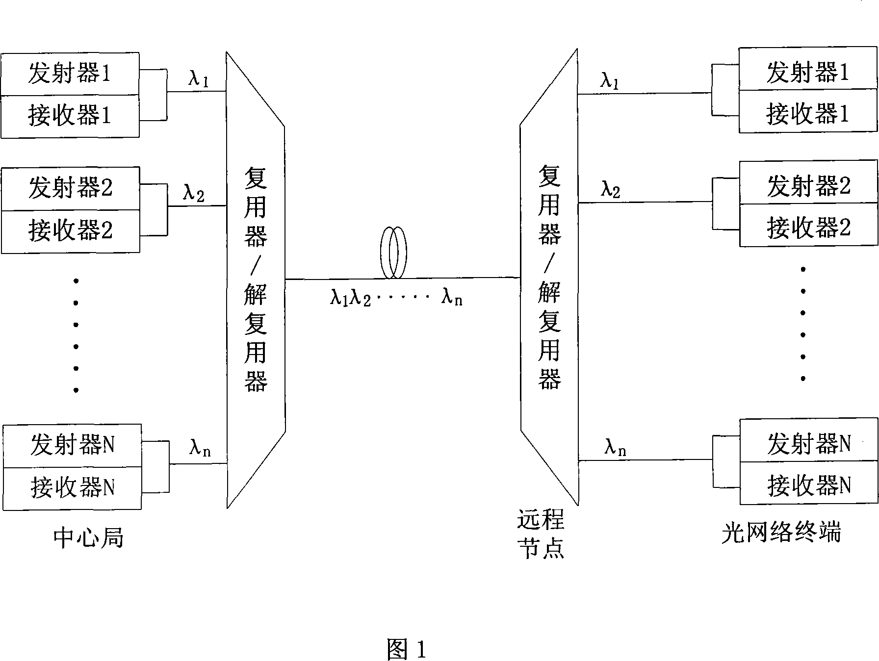
technical field [0001] The invention relates to the field of optical access networks, in particular to an optical fiber fault location equipment, method and device. Background technique [0002] Recently, with the continuous emergence of various data services, the demand for broadband access services has increased rapidly. In order to meet these high-bandwidth and large-capacity access needs, an ATM-based passive optical network (APON-ATM Passive Optical Network) has emerged. TDMA-PON ( Time Division Multiple Access-Passive Optical Network (Time Division Multiple Access-Passive Optical Network) network. However, due to the increase in user bandwidth requirements, and the TDMA-PON network is limited by the burst technology and only one transmission wavelength, it is difficult to expand the bandwidth and transmission capacity. To increase the bandwidth, it is necessary to increase the optical wavelength of user data transmission. At present, the WDM-PON-Wavelength Division M...

Claims


Application Information

Patent Timeline
IPC IPC(8): H04B10/08H04B10/12H04B10/071
CPCH04B10/071G01M11/3136H04J14/0221G01M11/3127H04B10/07H04B10/2581
Inventor 卫国梁波叶飞林华枫
Owner HUAWEI TECH CO LTD
Why Eureka
Try Eureka