Multi-headed isopach deep agitation driller

A deep mixing and equal thickness technology, applied in rotary drilling rigs, drilling equipment, earth-moving drilling, etc., can solve the problems of bit deviation and bifurcation, slow cutting speed and discontinuity.

Inactive Publication Date: 2007-12-05
JIANGSU HONGSHENG CONSTR ENG GROUP
View PDF0 Cites 8 Cited by
  • Summary
  • Abstract
  • Description
  • Claims
  • Application Information

AI Technical Summary

Problems solved by technology

From the point of view of construction technology, due to this and the past one-sequence, two-sequence or three-sequence wall formation, lap joints are used between piles, and the impact of the inherent rigidity of the drilling tool itself, during construction, the drill bit encountered The geological conditions encountered are complex, and it is easy to cause the deviation of the drill bit and bifurcation phenomenon due to the change of resistance. When used as an anti-seepage wall, the overlapping and lap joints between the columns are not sufficient to cause discontinuity, which makes it difficult to guarantee the construction accuracy.
In the construction of column-type continuous wall, if there is no large obstacle, the cutting speed is slow and the construction is carried out carefully, the vertical accuracy can be guaranteed, but the construction time and cost will increase, and the construction speed and construction accuracy depend entirely on The technical level of the mechanical operator; in addition, the overall permeability of the cut-off wall depends on its effective thickness. Since the columnar wall is arranged continuously in a cylindrical shape, the thickness is the smallest at the common chord position of the drill bit movement trajectory, and the seepage diameter is also the shortest , in order to achieve a sufficient design thickness, the diameter of the drill used must be increased, and the amount of cement slurry used is large, wasting a lot of resources

Method used


Image

  • Multi-headed isopach deep agitation driller
  • Multi-headed isopach deep agitation driller
  • Multi-headed isopach deep agitation driller

Examples


Embodiment Construction

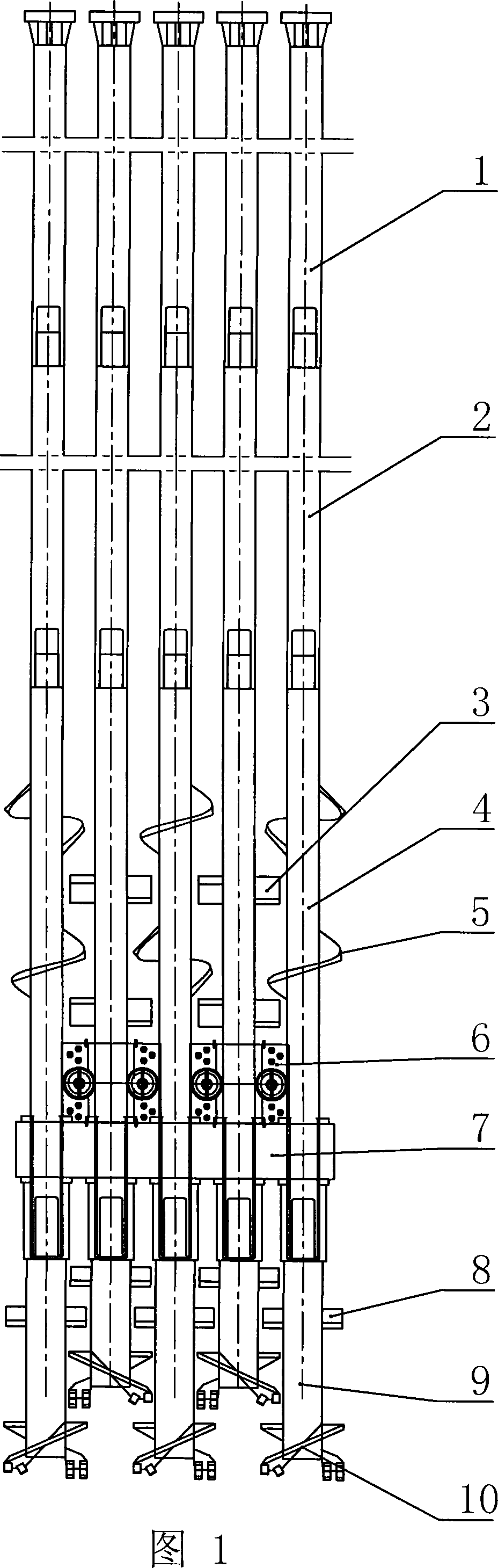
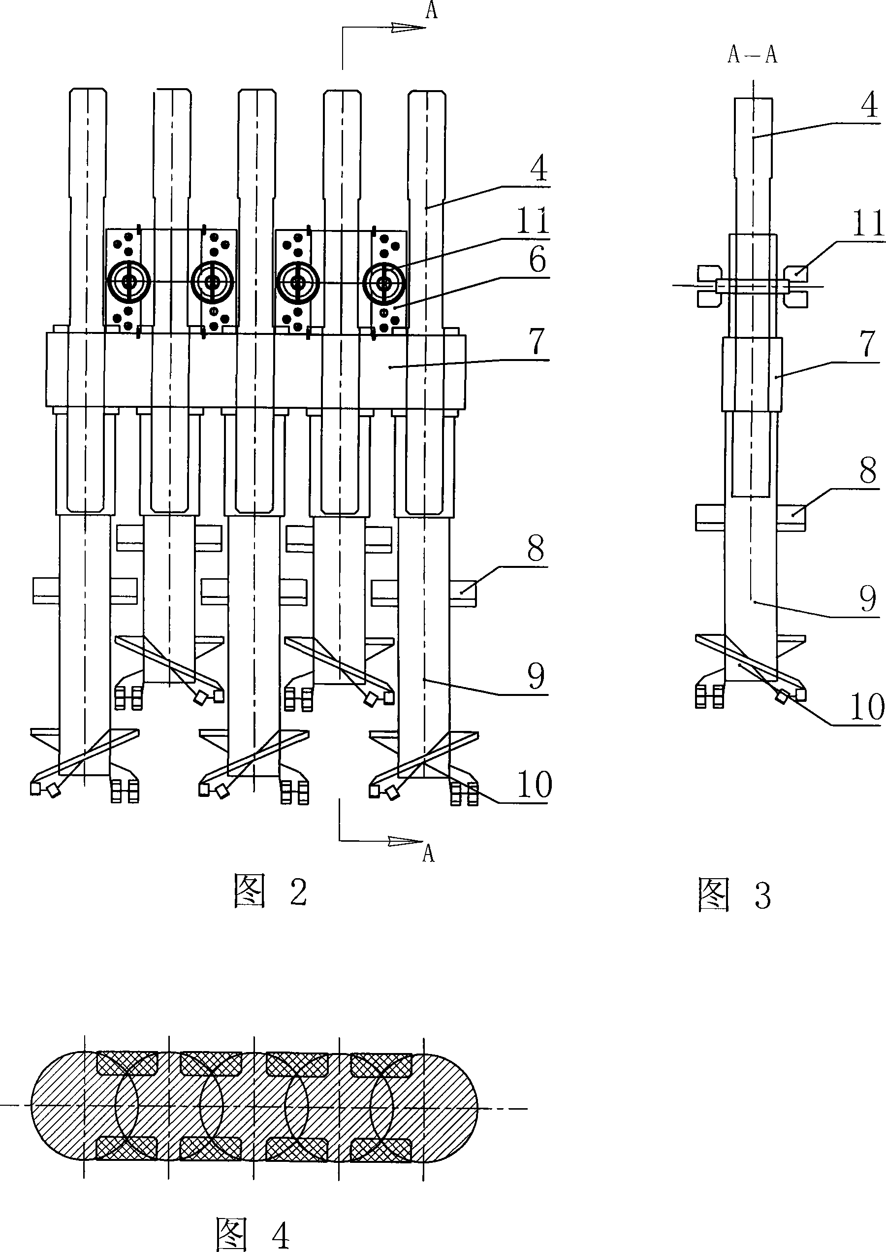
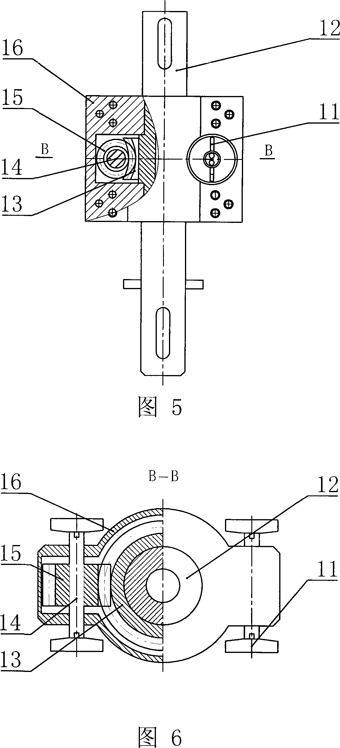
[0013] As shown in the figure, it is a multi-head equal-thickness deep-layer mixing drilling rig, including five groups of hollow drill rods arranged in parallel to each other. Each group of hollow drill rods is connected by upper drill rod 1, middle drill rod 2 and lower drill rod 4 from top to bottom. Composition, each lower drill rod 4 passes through the horizontally arranged cage 7 respectively, and the lower drill rod 4 on the upper part of the cage 7 is provided with a helical blade 5 and a stirring blade 3 along its axial direction, and the helical blade 5 and the agitating blade 3 can be set On the same lower drill rod 4, it can also be arranged on two adjacent lower drill rods 4 respectively, and the lower end of each lower drill rod 4 is equipped with a digging head, and the digging head is composed of a hollow digging rod 9, a twist drill bit 10 and a stirring blade 8 , the twist drill bit 10 is arranged on the lower end of the digging rod 9, the stirring blade 8 is ...


PUM


Abstract

The invention discloses a multithread equal-thickness deep mixing drill which belongs to the technology field of engineering drill. It is composed of more than two groups of upper and lower drill rocker parallel setting on the retainer. The retainer contains a wall cutter which contains a case hinging the retainer. A hollow turboshaft is coaxial fixed corresponding to the lower drill rocker on the case passing through it. A turbine is packaged outside the turboshaft. The worm meshing the turbine is set on its one or two sides. The worm shaft supports on the case against to the lower drill rocker and its two ends extending out of the case are equipped with wall cutting-tool. The longitudinal projection of the cutting-tool locates on the public chord extension line of the external turning trace of the two adjacent twist drills. The wall cutting-tool rotates to cut the border with the smallest separation between the adjacent round digging pores. The thicknesses of the digging pores are unified to get the equal-thickness underground serial wall. With the fewer materials and the greater strength, it is applied for the supporting water-seal of the foundation ditch and the levee antiseep.

Description

technical field [0001] The invention relates to an engineering drilling rig, in particular to an engineering drilling rig for drilling soil layers. Background technique [0002] At present, when the multi-head small-diameter deep-layer anti-seepage machine is used for anti-seepage treatment of embankments, column-type walls are used. There is a multi-head deep-mixing anti-seepage drilling rig for column-type underground diaphragm wall construction, which mainly includes at least two sets of hollow drill rods arranged in parallel to each other, and each set of hollow drill rods consists of upper drill rod, middle drill rod The lower drill rods are sealed and connected with the lower drill rods. Each lower drill rod is respectively inserted into the roller bushing center of the turntable, and is sealed with the middle and upper drill rods. The lower end of each lower drill rod is equipped with a drill bit. The drill bit has a hollow excavation rod, a drill bit and Composed of...

Claims


Application Information

Patent Timeline
Patent Type & Authority Applications(China)
IPC IPC(8): E21B3/025
Inventor 翟浩辉陈福坤吴平孙刚薛峰
Owner JIANGSU HONGSHENG CONSTR ENG GROUP
Why Eureka
Try Eureka