Single-track railway tunnel lining trolley

A technology for lining trolleys and single-track railways, applied in tunnel lining, tunnel, shaft lining, etc., can solve the problems of long load time, high labor intensity, and high construction cost, and achieve improved production efficiency, reduced labor intensity, and reduced construction costs. Effect

Inactive Publication Date: 2007-12-05
湖南五新智能科技股份有限公司
View PDF0 Cites 29 Cited by
  • Summary
  • Abstract
  • Description
  • Claims
  • Application Information

AI Technical Summary

Problems solved by technology

The disadvantage of this kind of tunnel lining trolley is that the size of the cross-section surrounded by the arch formwork is fixed, and for places with different tunnel sections, tunnel lining trolleys with different sections of the arch formwork are required, which makes the construction cost high. The production efficiency is low and the labor intensity is high; the hydraulic locking jacking cylinder has internal leakage in actual construction, and the concrete has a long process from pouring to solidification, so the jacking cylinder not only has a heavy load, but also has a long load time. As the load time increases, the piston rod of the oil cylinder will retract, resulting in the settlement of the formwork after being compressed, which will affect the quality of the tunnel lining; The center of the lining section deviates from the design center; only two door frames are used, and the formwork on both sides of the arch formwork is supported by the truss through the screw, which will cause the lateral force of the entire side formwork to concentrate on the truss, resulting in stress concentration. The force action line of the lateral jack does not pass the lateral force generated by pouring concrete through the side formwork, that is, the lateral jack is prone to small-scale instability, which will cause the concrete to run out of the mold during the molding process and reduce the quality of the lining surface, which is obviously not suitable Railway tunnel lining; since the formwork will have a certain bond with the concrete after casting, the formwork supported by the screw will not be demoulded even after the screw is loosened, and it needs to be removed piece by piece. The defect of screw support is that it is difficult to demould, and the second is that the manual workload is large
In addition, there is no support at the bottom of the side formwork of the existing tunnel lining trolley, so that the lower side formwork shrinks inward during pouring, resulting in a staggered joint between the formwork and the original concrete, thereby reducing the quality of the lining surface

Method used


Image

  • Single-track railway tunnel lining trolley
  • Single-track railway tunnel lining trolley
  • Single-track railway tunnel lining trolley

Examples


Embodiment approach 1

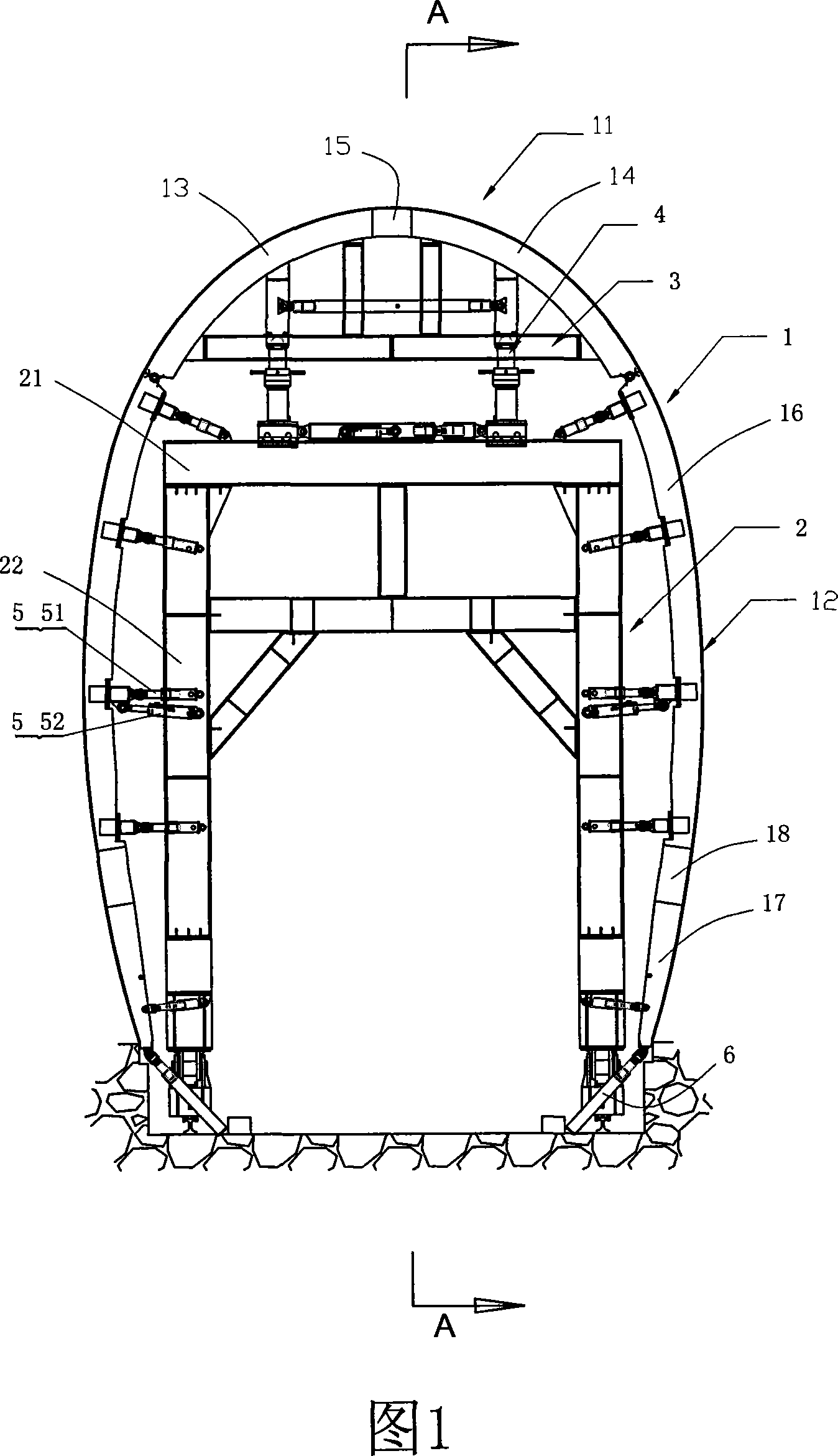
[0012] Embodiment 1: See Figure 1

[0013] It can be seen from Figure 1 that the present invention still includes the arched mold 1, the mast 2, the bracket 3, the jacking cylinder 4. The arched mold still includes the top template 11 and the two side templates 12, the top template 11 and the two sides The templates 12 are hinged, but the top template of the present invention is composed of a left top template 13, a right top template 14 and a top adjustment template 15. The left top template 13 and the right top template 14 are symmetrically located on the left and right sides of the top adjustment template 15. And connected by bolts, the top adjustment template 15 can be adaptively selected according to the width of the tunnel, either wide or narrow. Both sides of the template 12 are divided into an upper template 16 and a lower template 17, and a side adjustment template 18 can be added between the upper and lower templates, between the upper template 16 and the lower template ...

Embodiment approach 2

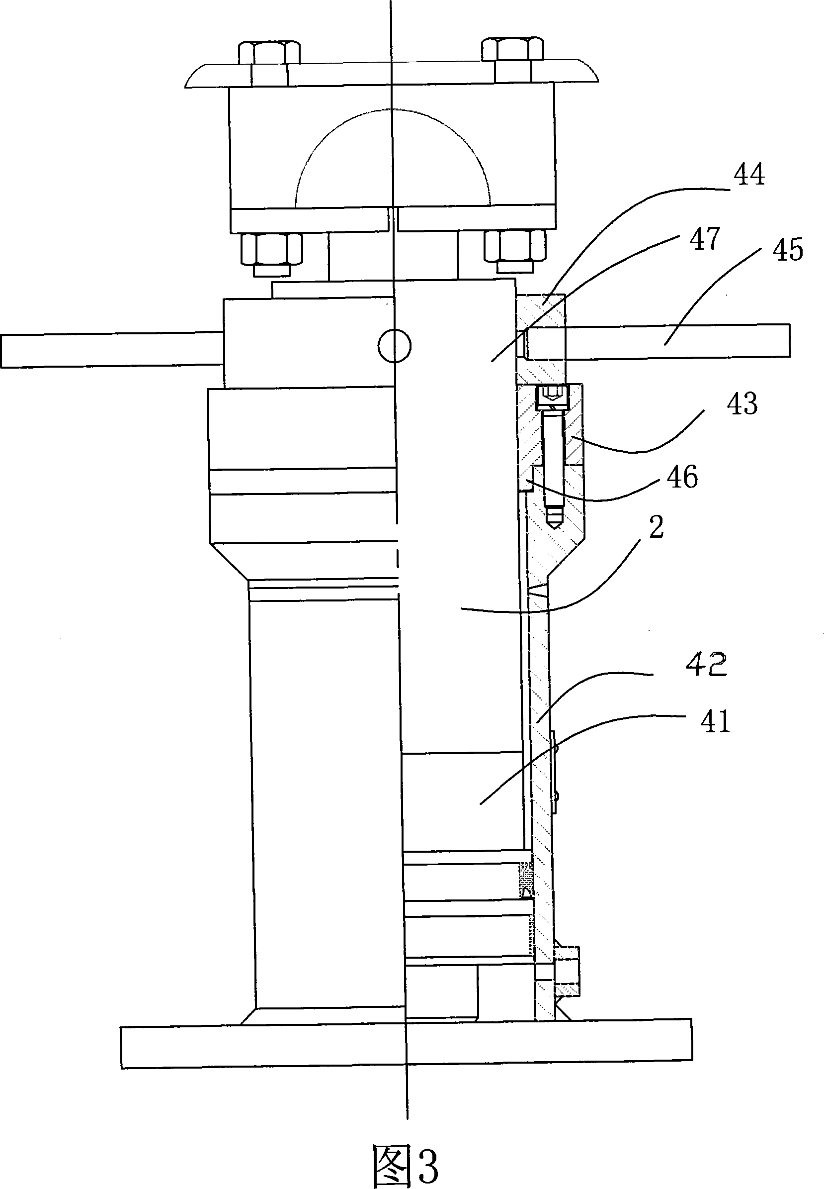
[0014] Embodiment 2: See Figure 3

[0015] This is an improved example of the jacking cylinder 4 based on the first embodiment.

[0016] In this embodiment, the jacking cylinder 4 still has a piston rod 41, a cylinder tube 42, and a guide sleeve 43, as well as a lock nut 44 and a handle 45. The guide sleeve 43 is provided with a step 46, and the guide sleeve 43 is mounted on the cylinder 42 One end, and its step 44 extends into the cylinder tube 42, the piston rod 41 extends from the guide sleeve 43, the extension section 47 of the piston rod 41 is provided with an external thread, the lock nut 44 and the outer thread on the piston rod 41 Threaded fit, the handle 45 is mounted on the lock nut 44. In this way, when the piston rod is subjected to a lateral force, it is ensured that the guide sleeve can reliably decompose the lateral force generated by the piston rod to the cylinder barrel, so as to ensure that the cylinder 42 and the guide sleeve 43 are only under pressure and not s...

Embodiment approach 3

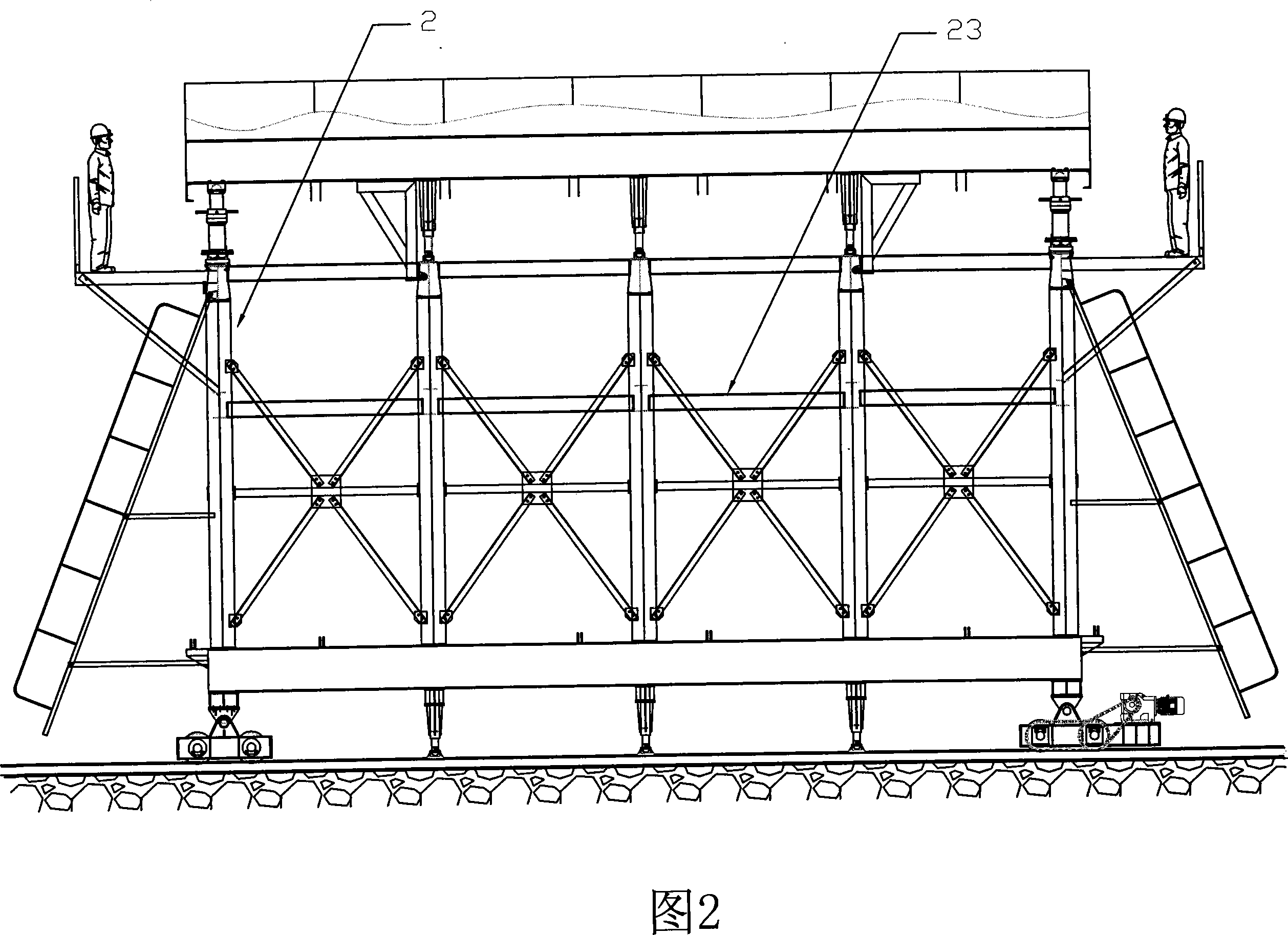
[0017] Embodiment 3: See Figure 1-Figure 2.

[0018] This embodiment is a single-track railway tunnel lining trolley very suitable for railway tunnels.

[0019] In this embodiment, the door frame 2 is rectangular, and is composed of an upper cross beam 21 and two upright columns 22. The two upright columns 22 are respectively located at the two ends of the cross beam 21 and are vertically and fixedly connected to the cross beam. At least three door frames 2 are used. In this embodiment, five door frames are used. These door frames are equidistantly arranged in the arch mold 1 and the door frames are connected by a truss 23. The supporting member 5 supporting the templates 12 on both sides adopts a number of jacks 51 and lateral cylinders 52. These jacks and lateral cylinders are evenly distributed at each mast 2 and installed symmetrically. One end is connected to the mast 2 and the other end is connected to the side. On the template, one of the lateral cylinders can be installed ...


PUM


Abstract

The invention discloses a lining platform car of the single-thread railway tunnel, which contains the arched mould including the roof and side follow boards, the bracket with a lifting cylinder, the gantry and the supporting component of the arched mould. It is characterized in that: the roof follow board contains the left and right roof follow boards in bilateral symmetry. There is an adjusting roof follow board for changing the sectional width between them. The side follow board contains the detachable upper and lower side follow boards. A side adjusting follow board for changing the sectional height and radius can be added between them. With the adjusting roof follow board and the side adjusting follow board, the sectional size of the arched mould can be adjusted in certain range to adapt the tunnel engineering with different sections. It can reduce the engineering cost, lighten the working strength and improve the working efficiency.

Description

Technical field [0001] The invention relates to a tunnel construction equipment, in particular to a single-track railway tunnel lining trolley. Background technique [0002] The well-known tunnel lining trolley mainly consists of a portal frame, a bracket and an arch mold. The portal frame is equipped with a jacking cylinder supporting the bracket and a supporting member supporting the arch mold. The cross section of the arch mold is fixed in size. No change, the jacking cylinder is fixed on the mast and adopts hydraulic locking cylinder. Generally, there are only two masts located outside the two ends of the arch mold. The centers of the two portal frames are connected by a truss. The formwork on both sides is supported by the truss by the screw rod, the supporting member is the screw rod, and there is no support at the bottom end of the side formwork of the arch mold. The disadvantage of this kind of tunnel lining jumbo is that the cross-section size enclosed by the arch form i...

Claims


Application Information

Patent Timeline
Patent Type & Authority Applications(China)
IPC IPC(8): E21D11/10
Inventor 王祥军王维兵龚俊谢亮
Owner 湖南五新智能科技股份有限公司
Why Eureka
Try Eureka