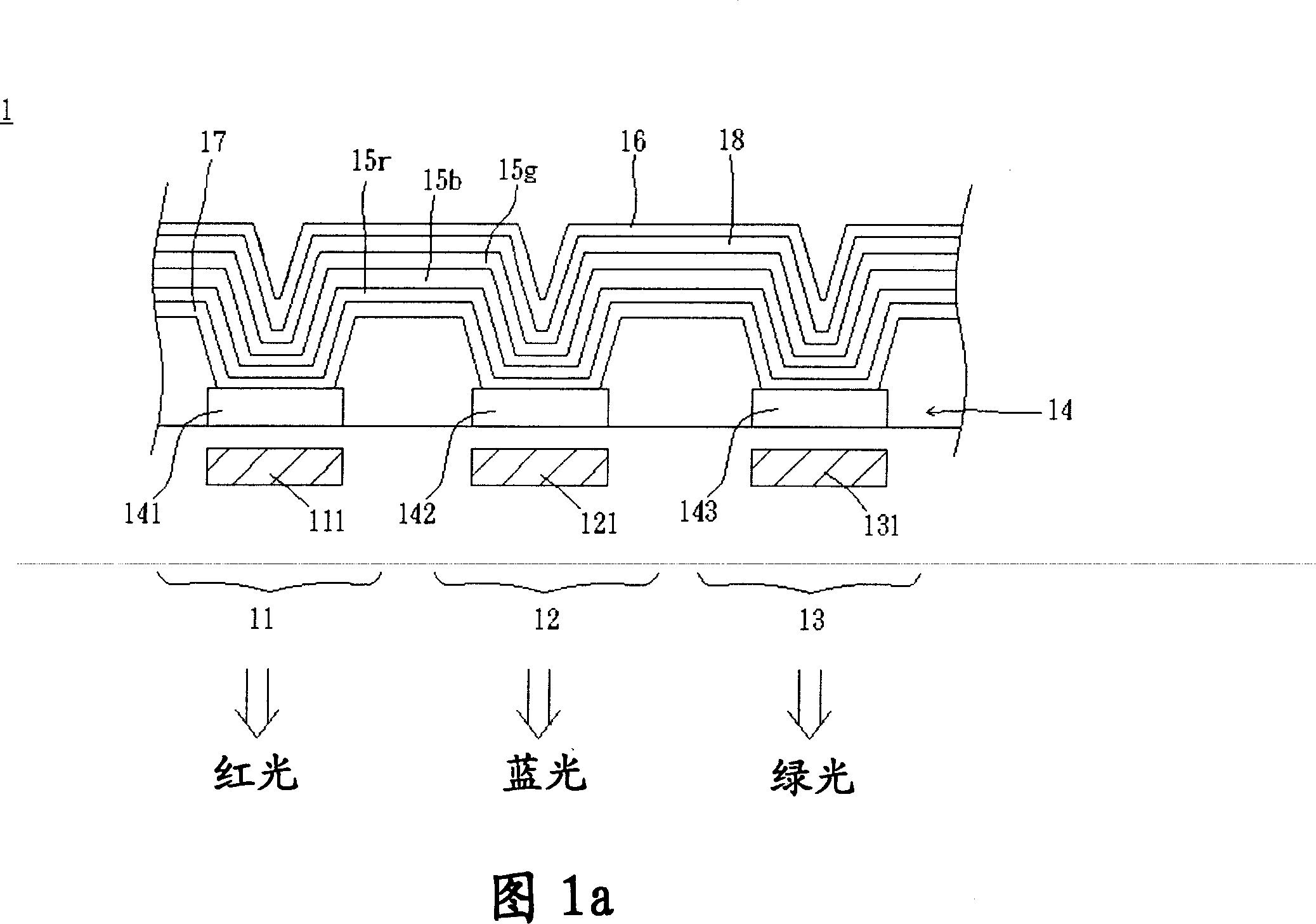
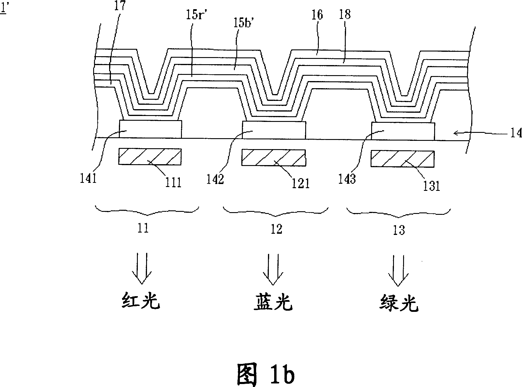
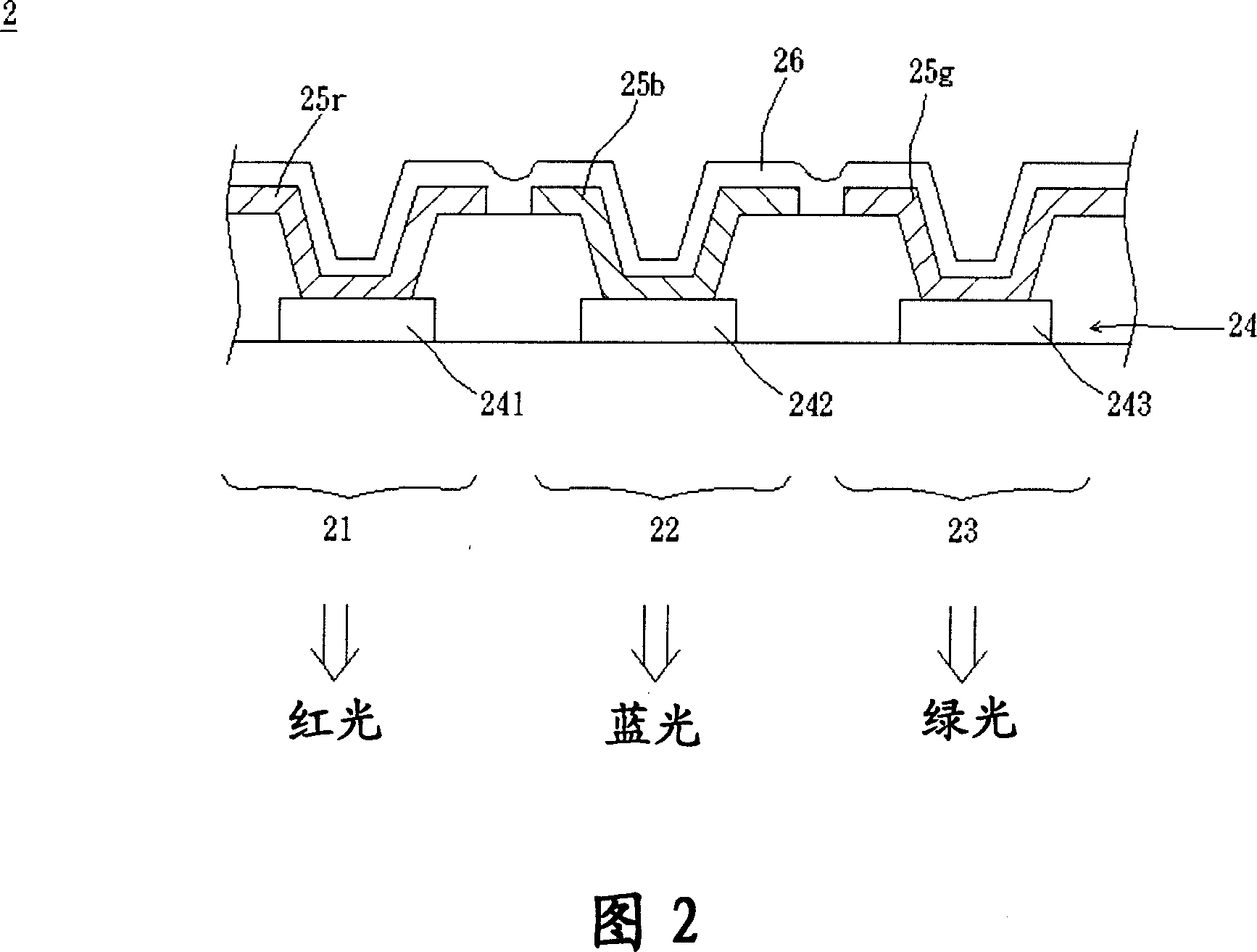
Display image system

An imaging system and organic light-emitting layer technology, applied in the direction of electrical components, electrical solid devices, circuits, etc., can solve the problems of product lack of structure and inconvenience, reduce production costs, reduce precision requirements and costs, and improve yield and efficiency Effect

Inactive Publication Date: 2007-12-05
INNOLUX CORP
View PDF0 Cites 9 Cited by
  • Summary
  • Abstract
  • Description
  • Claims
  • Application Information

AI Technical Summary

Problems solved by technology

[0011] It can be seen that the above-mentioned existing display image system obviously still has inconvenience and defects in structure and use, and needs to be further improved urgently.
In order to solve the problems existing in the display image system, the relevant manufacturers have tried their best to find a solution, but no suitable design has been developed for a long time, and the general products do not have a suitable structure to solve the above problems, which is obvious. It is a problem that relevant industry players are eager to solve

Method used


Image

  • Display image system
  • Display image system
  • Display image system

Examples


Embodiment Construction

[0057] In order to further explain the technical means and effects of the present invention to achieve the intended purpose of the invention, the specific implementation, structure, characteristics and effects of the display image system proposed according to the present invention will be described below in conjunction with the accompanying drawings and preferred embodiments. Details are as follows.

[0058] Please refer to FIG. 3, the display image system of the preferred embodiment of the present invention includes a plurality of pixels, and each pixel includes at least a first organic light-emitting element 31, a second organic light-emitting element 32 and a third organic light-emitting element. The element 33 and the organic light emitting elements 31 - 33 constitute a pixel 3 . The pixel 3 includes a first electrode layer 34 , a first organic light emitting layer 35 , a second organic light emitting layer 36 and a second electrode layer 38 . Wherein, the first electrode...


PUM


Abstract

The invention relates to a video display system, comprising plural pixels, each having first, second and third organic light-emitting component and comprising a first electrode layer, a first organic light-emitting layer, a second organic light-emitting layer, a second electrode layer and a filtering component, where the first organic light-emitting layer is arranged on the first electrode layer and inside the first and second organic light-emitting components; the second organic light-emitting layer is arranged on the first electrode layer, and inside the second and third organic light-emitting components, so as to make the first and second organic light-emitting layers overlap in the second organic light-emitting component; the second electrode layer is arranged on the first organic light-emitting layer and the second one; the filtering component is arranged in the second organic light-emitting component.

Description

technical field [0001] The invention relates to a display image system, in particular to a display image system with organic light-emitting elements. Background technique [0002] Organic light-emitting devices have the advantages of self-illumination, high brightness, high contrast, light and thin volume, low power consumption and fast response, and have been gradually applied to various image display systems. [0003] The organic light-emitting device mainly includes a cathode, an electron transport layer, an organic light-emitting layer, a hole transport layer and an anode, the organic light-emitting layer is arranged between the electron transport layer and the hole transport layer, and the cathode provides electron injection The transport layer and the anode provide hole injection into the hole transport layer. Electrons and holes are respectively emitted from the electron transport layer and the hole transport layer, and recombined in the organic light-emitting layer t...

Claims


Application Information

Patent Timeline
Patent Type & Authority Applications(China)
IPC IPC(8): H01L27/32
Inventor 西川龙司曾至国徐湘伦
Owner INNOLUX CORP
Why Eureka
Try Eureka