Tooth direction shaping gear hobbing processing technique

A processing technology and gear hobbing technology, which is applied in the field of gear tooth profile processing technology, can solve the problems of insufficient tooth surface hardness, steps in the tooth root, insufficient depth of the effective hardened layer, etc., and achieve the effect of uniform tooth surface hardness difference.

Active Publication Date: 2007-12-12
CRRC QISHUYAN INSTITUTE CO LTD
View PDF0 Cites 13 Cited by
  • Summary
  • Abstract
  • Description
  • Claims
  • Application Information

AI Technical Summary

Problems solved by technology

[0004] The purpose of the present invention is to provide a hobbing process for modifying the tooth direction, which can overcome the steps and effective hardened layer at the root of the tooth that exist in the traditional hobbing process when processing large tooth direction modification. Shortcomings such as insufficient depth and insufficient tooth surface hardness can meet the requirements of modern advanced gear design

Method used


Image

  • Tooth direction shaping gear hobbing processing technique
  • Tooth direction shaping gear hobbing processing technique

Examples


Embodiment Construction

[0015] The gear hobbing process for tooth profile modification includes:

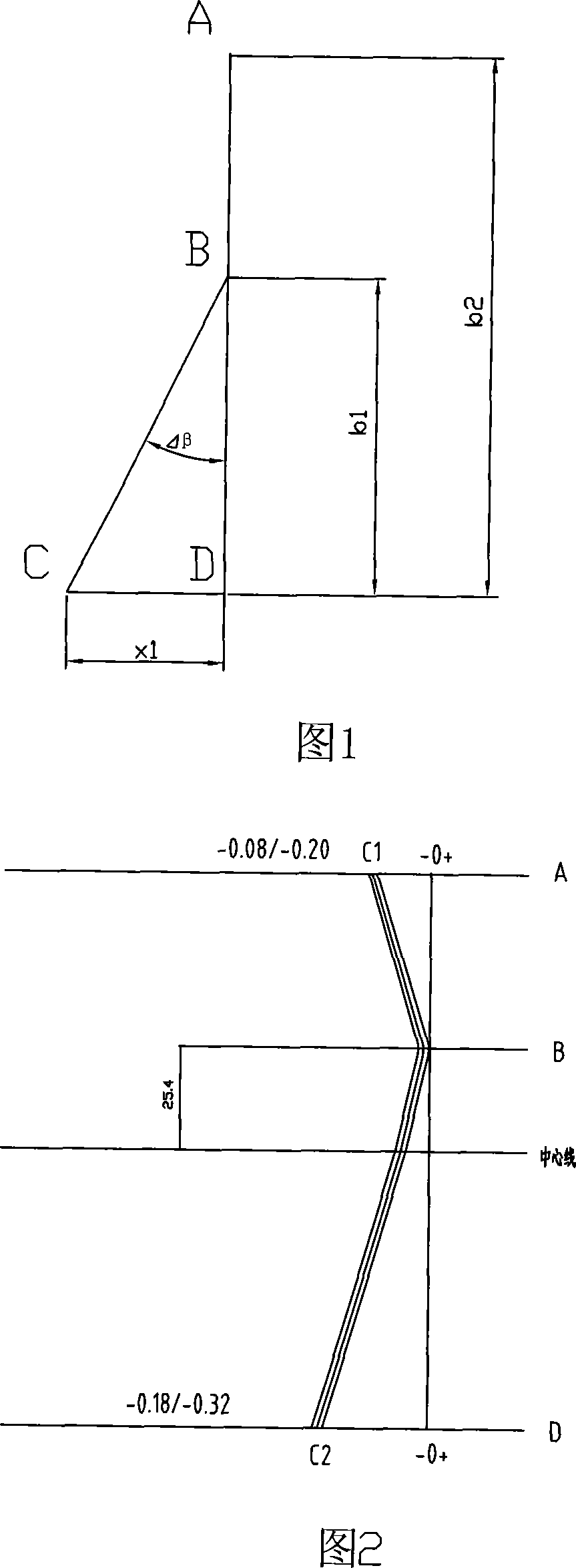
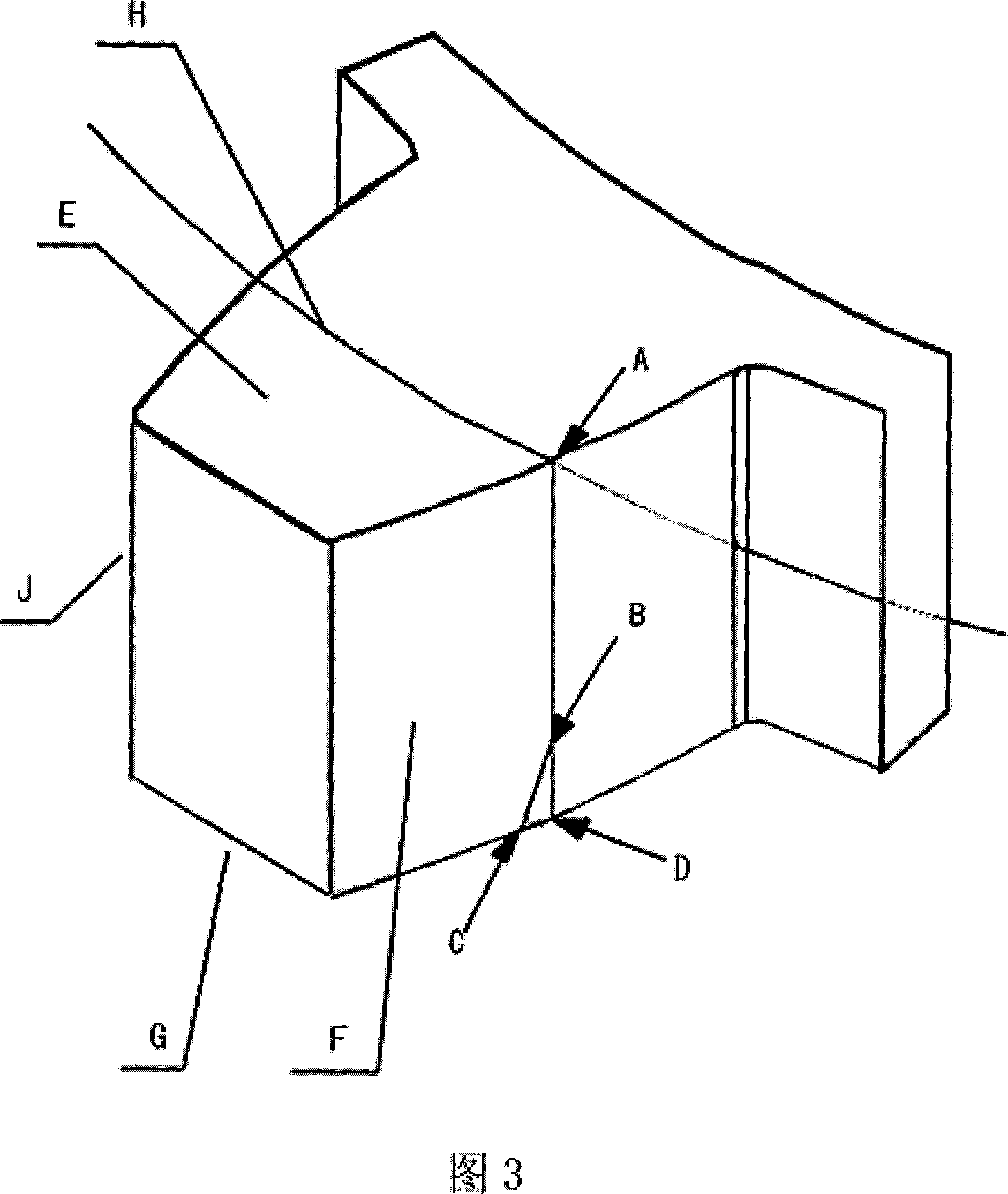
[0016] a. According to the requirements of the hobbing drawings, according to the requirements of the hobbing drawings, hob the outer diameter of the gear blank to the common normal line of the gear or exceed a certain distance; then use the hobbing machine to process the gear hobbing to the tooth width of the gear. The detection point A or detection point D of the end surface, wherein, the detection point A is located at the intersection of the tooth surface F forming the gear groove and one end surface E of the gear and the intersection of the pitch circle H of the gear, and the detection point D is located at the intersection of the tooth surface F forming the gear groove The intersection point of the intersection line between the tooth surface F and the other end surface G of the gear and the pitch circle H of the gear;

[0017] b. Based on the actual helix angle of the CB line and the parameters of...


PUM


Abstract

The invention relates to the machining of gear teeth. The machining process comprises: Based on the drawing, it uses the hobber machining the gear to the inspection point A or D, computing the differential change wheel angle t based on the hobber differential mechanism with CB line actual spiral angle and gear and hobber parameter, loosening the differential change wheel, holding the change angle t, imitating the difference of machining small spiral gears, forming fixing point from the end surface fixing theoretical point C. It can get rid of the deficiencies of step, insufficient effective hardening and teeth surface hardness.

Description

technical field [0001] The invention relates to a gear tooth shape processing technology, in particular to a gear hobbing technology with relatively large tooth direction modification. Background technique [0002] With the development of modern industry and the promotion of mathematical theory, the gear transmission system is developing towards high speed, heavy load, small volume and low weight. In order to meet the needs of the development of the gear transmission system, sometimes the designed gears are required to have a relatively large tooth direction modification, especially the asymmetrical tooth direction modification of the left and right tooth surfaces. If this kind of gear adopts the traditional hobbing and grinding process, there will be a defect that is absolutely not allowed in the design where the tooth modification amount is large after the grinding. These disadvantages are (1) there are steps in the tooth root; (2) the depth of the effective hardened laye...

Claims


Application Information

Patent Timeline
IPC IPC(8): B23F5/20
Inventor 吴国庆吴刚徐康琪
Owner CRRC QISHUYAN INSTITUTE CO LTD
Why Eureka
Try Eureka