Tunneling, anchoring and drilling composite machine

The technology of compound machine and drilling machine is applied in the fields of bolt-digging compound machine, drilling machine integrated new model, bolting machine and roadheader, which can solve the problems of low work efficiency, limitation of empty head distance, complicated hydraulic system, etc. , to achieve the effect of improving work efficiency, reducing space size, and simplifying design structure

Inactive Publication Date: 2007-12-12
SANY HEAVY EQUIP
View PDF4 Cites 27 Cited by
  • Summary
  • Abstract
  • Description
  • Claims
  • Application Information

AI Technical Summary

Problems solved by technology

[0005] 1. The bolter is installed on the rotary table of the roadheader, and the height of the machine is too high, which affects the performance of the roadheader
[0006] 2. The cantilever of the main arm is too long and the stability is not good
[0007] 3. There is no support when the side anchor is installed, and the failure rate is high during work.
[0008] 4. The working position of the bolter is too high to be suitable for bolting operations in low roadways
[0011] 1. Installed on the upper part of the rotary table of the roadheader, the empty head distance is limited, and the low roadway bolt cannot be drilled
[0012] 2. The rock bolt rig has no self-rotating device, so the angle bolt cannot be drilled
[0013] 3. The function of the cutting part of the roadheader is not used, and there are few positions for bolting
[0014] 4. The cantilever of the main arm is too long and the stability is not good
[0015] 5. Only suitable for roadways with rectangular or trapezoidal sections
[0018] 1. Installed on the rotary table of the roadh

Method used


Image

  • Tunneling, anchoring and drilling composite machine
  • Tunneling, anchoring and drilling composite machine

Examples


Embodiment Construction

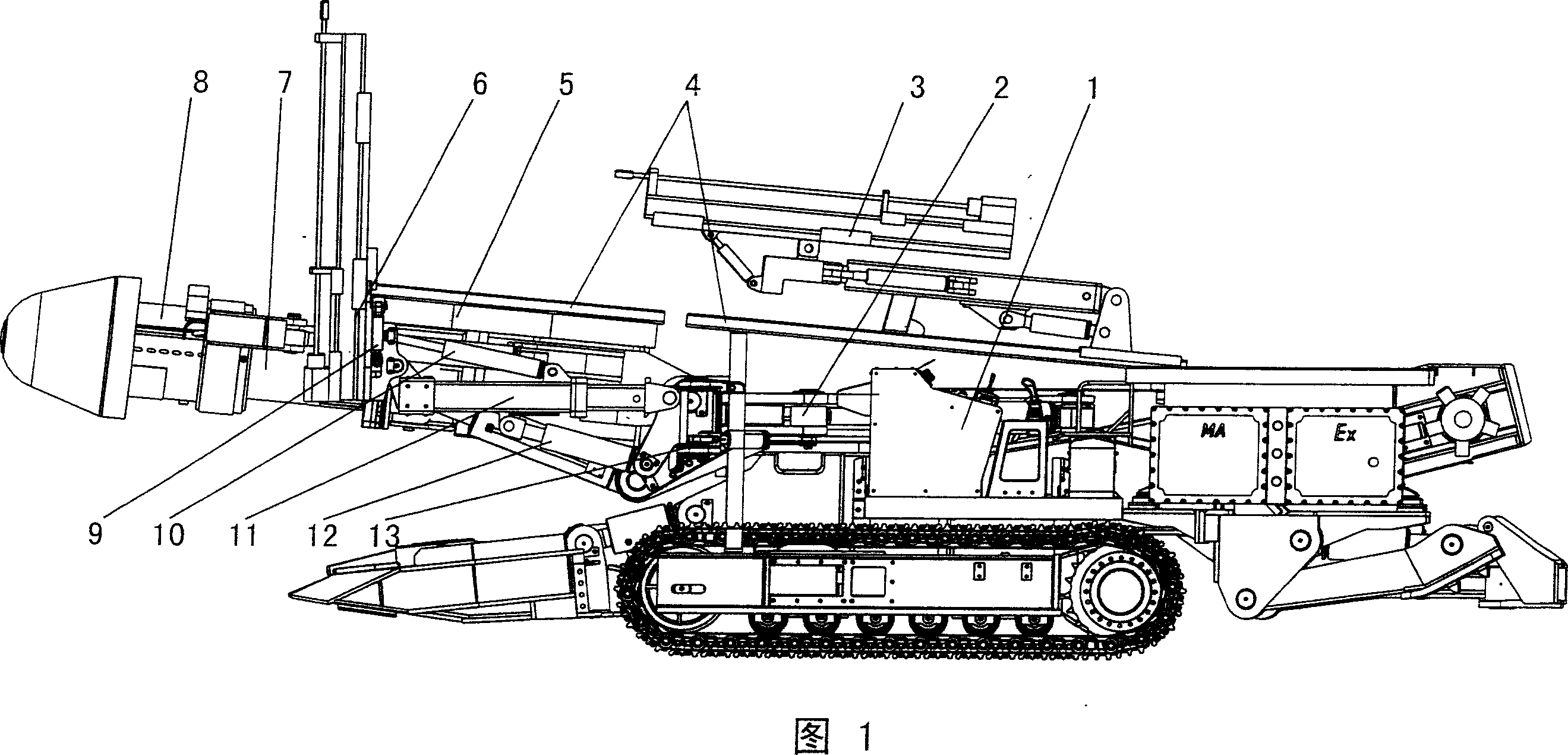
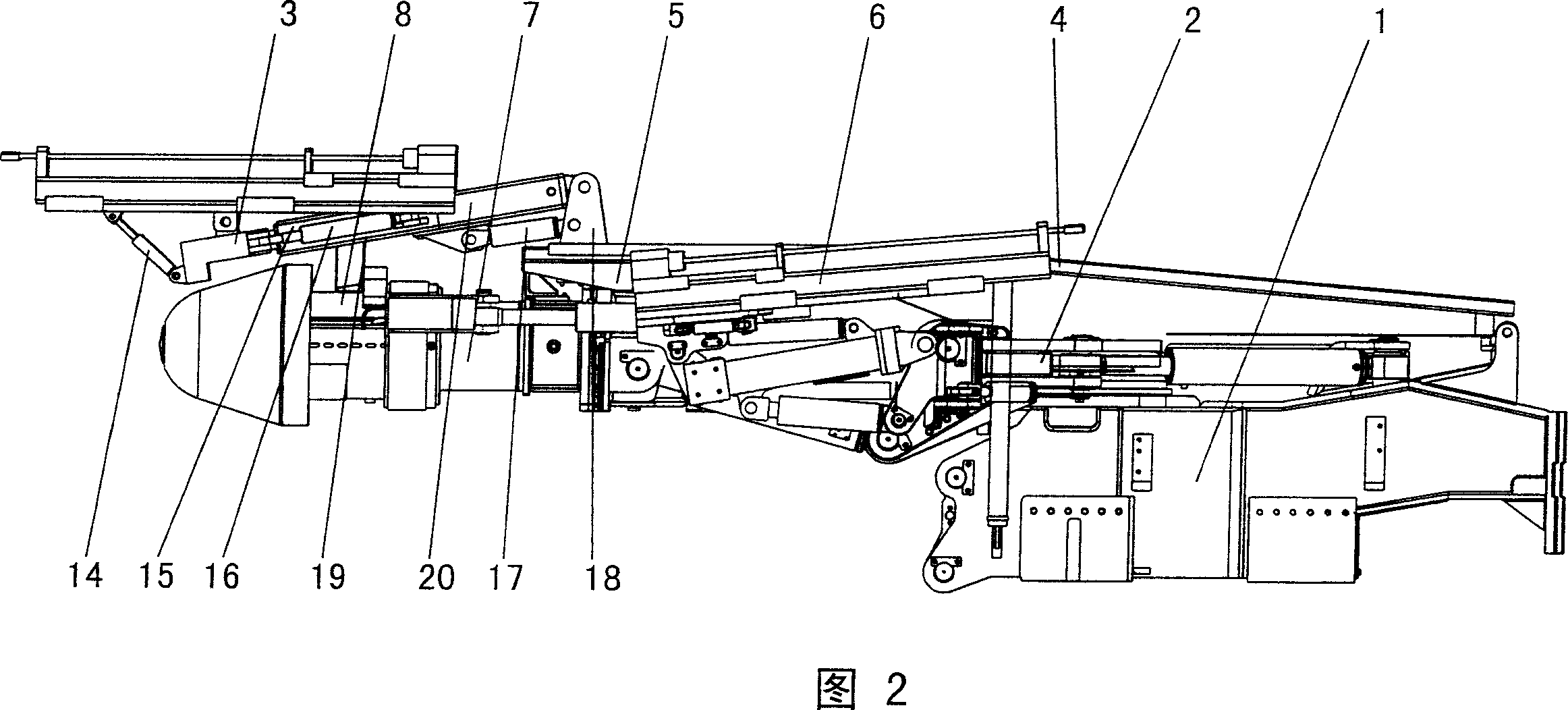
[0042] As shown in Figures 1-2, the present invention is a combined machine for digging, bolting and drilling, and the three machines of the roadheader, bolter and drilling machine are installed in one. The drilling machine 3 is installed on the upper part of the heading machine 1, and the drilling machine 3 and the heading machine 1 are connected by a track 4. The part above the tunneling machine 1 in the figure is the drilling machine 3 device. Together with the cutting part 7 of the roadheader 1, it can perform lifting and swinging motions, coupled with its own rotation and other functions, to complete the deep hole drilling of the roadway; the bolter 6 is symmetrically installed on the sidewall of the roadheader turret 2 , The bolter 6 and the boring machine turntable 2 are hinged by a hydraulic cylinder. In the figure, the oil cylinders on both sides of the front and their supporting parts are the bolter 6 device, which together with the cutting part 7 of the roadheader 1 swi...


PUM


Abstract

The invention involves a composite machine which integrals the boring machine, the bolting machine and the drilling machine into one unit, specifically it is a boring surveying operation which uses the boring machine cutting part armor plate as the working platform of drilling machine, uses the cutting head as the main support of drilling machine, achieves the integration of drilling machine and the boring machine cutting part and completes the boring surveying work of tunnel deep hole through the lifting , swinging of cutting part and the self-functions; at the same time, it also uses that the boring machine panoramic table side wall can be installed folded bolting machine device to achieve the tunnel-dislodging anchor bar anchor-installing operation of automatic hydraulic control anchor bar machine. The installation of 'three machines' into one unit: the drilling machine is installed on the boring machine through rail connection; the bolting machine is positioned and installed on the side wall of boring machine panoramic table through straight pins and high strength bolt connection, the bolting machine and the drilling machine both use the lifting and the swinging functions of boring machine cutting part fully, greatly simplify the design structure of boring machine bolting machine, reduces the space size of boring, bolting and drilling composite machine on the maximum extent.

Description

Technical field [0001] The invention relates to a coal mine tunnel excavation and bolting and drilling protection machinery, specifically a new integrated model of a roadheader, a bolter and a drilling machine-a combined machine for digging and bolting, which realizes the effect of three-machine integration and continuous operation. Background technique [0002] At present, the support work of roadway tunneling machine after tunneling is a arduous, complicated and extremely inefficient work. The main reason is that the split work of the tunneling machine and the bolter causes a lot of waste of time, and the effective working time is very small. , Manual bolting is not only labor-intensive, but also very low-efficiency. For high gas roadways, the roadheader needs to drill about 15 gas release holes with a diameter of 100 mm and a depth of more than 20 meters in the front section before digging. At present, it is also completely completed by manual operation. Manual drilling and pe...

Claims


Application Information

Patent Timeline
IPC IPC(8): E21C25/66E21B3/00E21D20/00
Inventor 顾天喜梁坚毅李恩龙陈锷李勇
Owner SANY HEAVY EQUIP
Why Eureka
Try Eureka