Ultraviolet radiation device and cutting machine with the same

A technology of irradiation device and ultraviolet light, which is applied to fine work devices, manufacturing tools, stone processing equipment, etc., can solve the problems of reduced strength, time required, and productivity problems, and achieve the effect of suppressing the number of use

Active Publication Date: 2010-06-02
DISCO CORP
View PDF4 Cites 0 Cited by
  • Summary
  • Abstract
  • Description
  • Claims
  • Application Information

AI Technical Summary

Problems solved by technology

However, since the light intensity of the ultraviolet irradiation lamp decreases with the passage of time, it is necessary to periodically adjust the irradiation time or replace it regularly, so it takes time to adjust and replace it, and there is a problem in terms of productivity.

Method used


Image

  • Ultraviolet radiation device and cutting machine with the same
  • Ultraviolet radiation device and cutting machine with the same
  • Ultraviolet radiation device and cutting machine with the same

Examples


Embodiment Construction

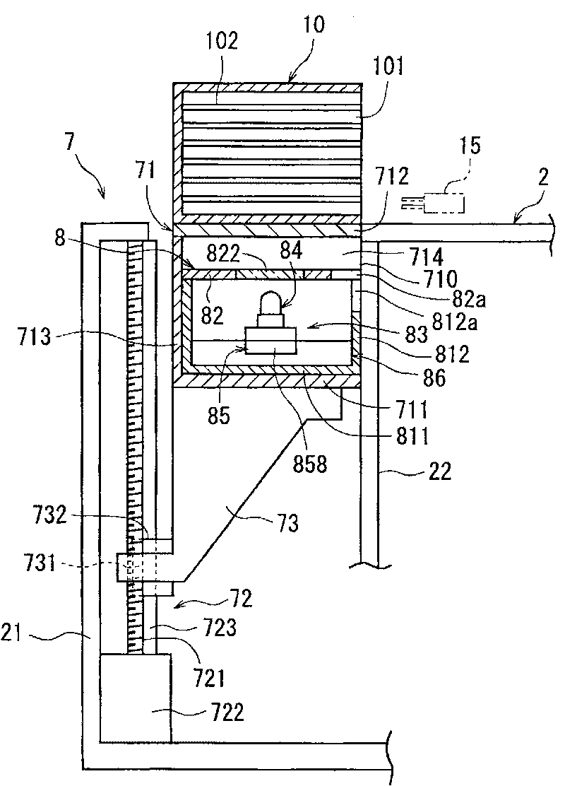
[0029] Hereinafter, preferred embodiments of the ultraviolet irradiation device and the cutting machine provided with the ultraviolet irradiation device of the present invention will be described in detail with reference to the drawings.

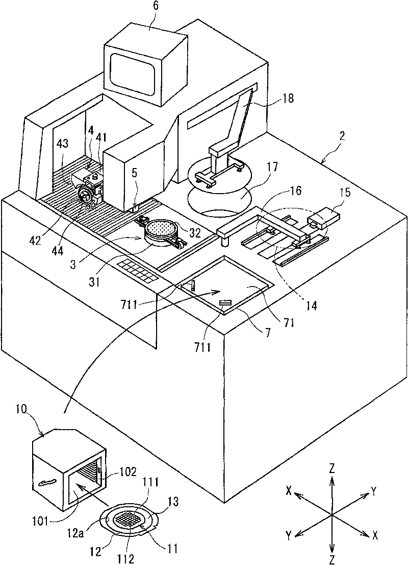
[0030] figure 1 The middle is a perspective view of a cutting machine equipped with an ultraviolet irradiation device according to the present invention.

[0031] The cutting machine according to the illustrated embodiment includes a substantially rectangular parallelepiped body casing 2 . In the body casing 2, a chuck table 3 for holding a workpiece is arranged movably along the cutting feed direction, that is, the cutting feed direction indicated by an arrow X. As shown in FIG. A chuck table (chucktable) 3 includes a suction cup support body 31 and a suction suction cup 32 mounted on the suction cup support body 31, and is held on the surface of the suction suction cup 32, that is, the mounting surface, by a suction mechanism not shown. ...


PUM


Abstract

The invention provides an ultraviolet irradiation device which avoids the reduce of light intensity and stably supplies ultraviolet, and cutting machine with the ultraviolet irradiation device. The ultraviolet irradiation device comprises: shell with hatch upside, ultraviolet irradiation element which is located in the shell, and cover element which covers the hatch of the shell and includes a ultraviolet through area which lets the ultraviolet of the ultraviolet irradiation element through the area. The ultraviolet irradiation element comprises: light emitting diode installation component, plenty of ultraviolet light emitting diodes arranged on the light emitting diode installation component in the range of longer than the diameter of wafer, and movement component which moves the light emitting diode installation component to the orthogonal direction of the arranging direction of the plenty of ultraviolet light emitting diodes.

Description

technical field [0001] The present invention relates to an ultraviolet irradiation device for reducing the adhesive force of the adhesive tape by irradiating ultraviolet rays to an adhesive tape to which wafers such as semiconductor wafers are bonded, and to a cutting machine provided with the ultraviolet irradiation device. Background technique [0002] For example, in a semiconductor wafer manufacturing process, the surface of a substantially disc-shaped semiconductor wafer is divided into a plurality of regions by pre-segmentation lines called streets (streets) arranged in a grid, and in the divided regions Form circuits such as ICs and LSIs. Then, individual semiconductor chips are manufactured by dicing the semiconductor wafer with a cutting machine along the dicing line. [0003] When dicing a semiconductor wafer with a cutting machine as described above, the divided semiconductor chips are bonded in advance to the surface of the adhesive tape mounted on the semicondu...

Claims


Application Information

Patent Timeline
Patent Type & Authority Patents(China)
IPC IPC(8): H01L21/00H01L21/301H01L21/78H01L21/67B28D5/00
Inventor 畑亮
Owner DISCO CORP
Why Eureka
Try Eureka